
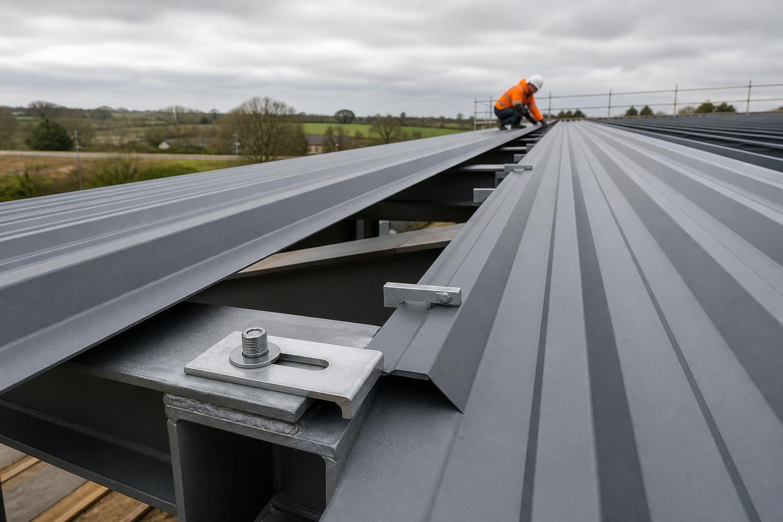
How should roof cladding systems accommodate thermal movement?
Roof cladding systems accommodate thermal movement through correctly designed fixings, laps, joints and support details that allow panels to expand and contract without imposing excessive stress on the sheets or structure. Material selection, panel length, temperature range and the positions of fixed and sliding connections should be assessed together during design and installation.
Thermal movement is accommodated by treating the roof as a coordinated build-up rather than as isolated sheets. As temperature changes, the cladding, secondary steelwork, insulation, liners, flashings and sealants can respond at different rates. A suitable design therefore controls where movement occurs, prevents it being transferred into vulnerable details and maintains the weather seal throughout the expected service life.
Why movement occurs
Solar radiation can make the outer sheet substantially warmer than the surrounding air, while the underside remains cooler. The roof may also experience rapid changes between direct sunlight, cloud cover and low night-time temperatures. Dark finishes generally absorb more solar heat than light finishes, and long, uninterrupted roof runs develop more cumulative movement than short panels. Internal conditions can create a separate temperature regime, particularly in buildings with heating, refrigeration, livestock, machinery or process equipment.
Movement is not limited to expansion along the roof slope. Sheets can also change across their width, and individual layers may move by different amounts. This differential movement is important in insulated systems: the outer weather sheet, insulation, vapour control layer and liner may not all share the same temperature or coefficient of expansion. If they are forced to behave as one rigid component, stresses can accumulate around joints, penetrations and perimeter details.
Establishing a controlled movement path
The designer should identify the parts of the roof that need to remain restrained and the parts that must accommodate relative movement. This includes checking the interaction between roof sheets and purlins, ridge and eaves details, verge construction, wall interfaces and any changes in roof direction. A clear movement strategy avoids relying on sealants or thin flashings to absorb movement for which they were not designed.
Where a roof is divided into separate runs, the division should be coordinated with the structural layout and weathering details. Movement zones may require specially formed cover pieces or support arrangements so that one section can respond without dragging adjacent sections with it. Their geometry must shed water, resist wind actions and remain compatible with the roof profile.
Fastener and hole detailing
Fasteners must be selected and installed so that they provide the required restraint without distorting the sheet or preventing its intended movement. Excessive tightening can crush the profile, damage washers and create local stress concentrations. Misaligned holes, over-drilling, burrs and swarf can similarly compromise both the metal and the seal.
Slotted or clearance-hole arrangements may be appropriate in specific movement details, but they must be designed with adequate edge distances, washer sizes and sealing provisions. The direction of permitted movement matters: a detail that allows travel along the sheet but restrains it across the sheet may behave differently from one with the opposite orientation. Site installers should follow the approved fixing pattern rather than enlarging holes or altering fastener positions to resolve fit-up problems.
Joints, laps and weather seals
Joints should retain sufficient overlap and sealing contact when the adjacent components move. Sealants need to be compatible with the substrates, remain elastic over the expected temperature range and be applied to clean, dry surfaces in accordance with the system specification. A seal that is too rigid may split or pull away; one that is applied too thickly or without proper backing may also fail to accommodate repeated movement.
Lap orientation, drainage direction and the position of stitch fixings should be considered together. Water must not be directed towards a movement joint or trapped behind a cover flashing. At ridges, verges and abutments, flashings should be shaped and supported so that they can follow movement without buckling, tearing or opening a path for wind-driven rain.
Penetrations and attached components
Rooflights, ventilators, extraction equipment, access hatches, pipework and other penetrations can interrupt the normal movement of a roof. Each opening needs an adequately sized weathering detail, with independent support where the attached item is heavier or more rigid than the cladding. Fixing a rigid service or frame directly across a movement zone can lock the roof in place and transfer forces into the surrounding sheets.
Where equipment spans more than one structural bay, the support arrangement should be reviewed for differential movement and maintenance access. Flexible connections, separate curb construction or movement-capable flashings may be needed, depending on the equipment and roof build-up. The same principle applies to gutters, parapets and wall cladding that meet the roof: the junction must not assume that all adjoining elements will move together.
Installation and quality checks
Installation conditions affect how much movement capacity remains after completion. Sheets should be positioned accurately before permanent fixing, and cut edges should be free from distortion. The installer should check that fixing washers are seated correctly, profiles have not been crushed and cover flashings are not trapped by unintended fasteners. Sealant continuity, lap cleanliness and the unobstructed operation of any designed movement detail should be inspected before handover.
Design drawings should identify movement-sensitive areas clearly, including changes in roof geometry, long runs, penetrations and interfaces with other materials. Fabrication drawings and site details need to agree so that allowances are not lost during manufacture or erection. If the roof is altered later, new openings, signs, solar equipment or service supports should be assessed for their effect on the original movement strategy rather than added without review.
Correctly coordinated detailing allows thermal strain to be distributed through the roof in a predictable way. It reduces the risk of distorted sheets, failed seals, noisy movement, leakage and premature corrosion while preserving the structural and weathering performance of the complete cladding system.
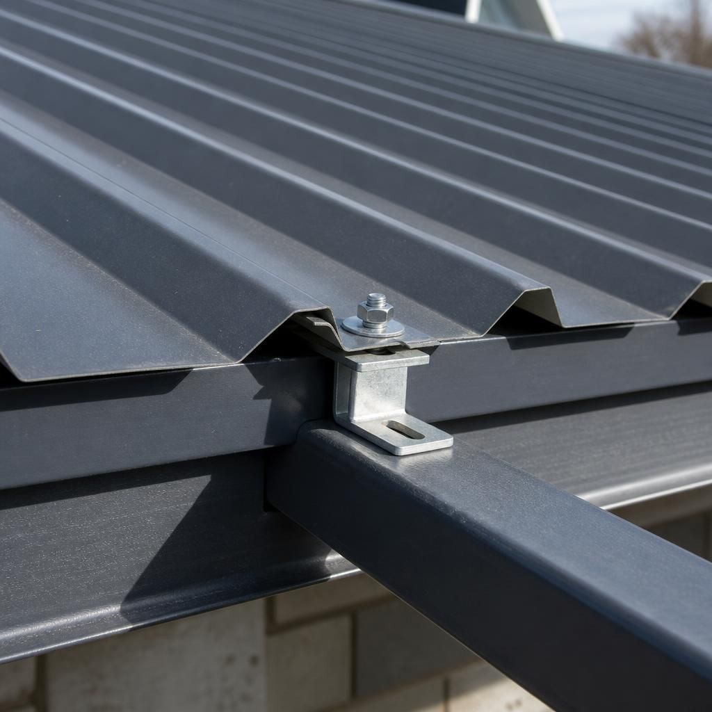
A thermal movement allowance is the amount of expansion or contraction reserved within a roof cladding detail after the system has been fixed. It should be assessed for the expected temperature range, panel length, material properties and installation temperature, rather than treated as a nominal gap.
Installation temperature is particularly important. If a long panel is fixed when it is already near one extreme of its expected temperature range, most of its subsequent movement may occur in one direction. The design and setting-out information should therefore establish:
- the reference condition from which movement is assessed;
- the direction and extent of permitted travel;
- the location of restraint and movement-capable connections; and
- the remaining clearance at covers, flashings and penetrations.
This approach allows the available movement capacity to be checked before installation and makes it easier to identify details that could become tight, overstressed or visually distorted as temperatures change.