

How is the load capacity of a roof cladding system assessed?
Roof cladding system load capacity is assessed through structural calculations that consider the cladding profile, material, span, fixings and supporting frame, together with imposed loads such as wind, snow and maintenance access. The calculated actions are checked against the system’s resistance and serviceability limits to confirm that deflection, fastener performance and overall stability comply with the applicable design requirements.
Load capacity is established by comparing the actions imposed on a roof cladding assembly with the resistance of every part of that assembly. The assessment covers the sheets or panels, laps, fasteners, purlins, rails and primary steelwork, rather than treating the cladding as an isolated surface.
The process normally begins with the design information for the building. This includes the roof geometry, cladding profile, steel thickness, support spacing, sheet orientation, lap arrangements, openings, edge zones and the intended use of the roof. The proposed fixing pattern is also important because a sheet can have adequate material strength but still fail if the fasteners or supports are inadequately spaced.
- Dead loads: the self-weight of the cladding, insulation, liner panels, flashings, services and any permanently attached equipment.
- Wind actions: pressure and suction on the roof, with particular attention to corners, perimeters and exposed elevations where local forces can be higher than those over the main roof area.
- Snow actions: the general roof load and any drift or accumulation caused by changes in level, parapets, adjoining roofs or roof-mounted obstructions.
- Maintenance actions: temporary loads associated with inspection and maintenance, applied only where the system is designed to support them. A roof should not be assumed to be walkable merely because it can resist ordinary environmental loads.
- Construction actions: loads that may occur while sheets, insulation, plant or materials are being installed, where these are relevant to the design sequence.
These actions are combined in accordance with the applicable UK structural design standards. Separate checks are made for ultimate limit states, which consider strength and stability, and serviceability limit states, which consider deflection, vibration, appearance and continued weather performance. The governing combination is not always the one producing the greatest overall load; suction, for example, may control the pull-out or pull-over resistance of the fasteners even when downward loading is modest.
The cladding itself is checked for bending between supports, local distortion around fixings, bearing at the purlins and failure at sheet ends or side laps. Profile geometry has a direct effect on these checks. Deeper profiles may span further, but their stated capacity still depends on the support arrangement, steel grade, thickness, restraint and the particular loading case. Manufacturer load tables or tested data can assist with this assessment, provided the project conditions match the assumptions behind the data.
Fastener design is assessed separately and as part of the complete load path. Checks can include pull-out from the supporting steel, pull-over through the sheet, shear, tension, combined actions, washer performance and the capacity of the lap connection. The number and position of fixings, support thickness and edge distances all affect the result. On a roof subject to wind suction, the perimeter and corner fixing arrangements commonly require closer scrutiny than the internal roof area.
Deflection is checked under the relevant service loads to prevent excessive ponding, impaired drainage, damage to finishes, opening of laps or stress on flashings and seals. Where insulation or a liner is part of the build-up, its ability to tolerate movement and maintain support must also be considered. A cladding system may therefore be strong enough in a collapse check but unsuitable if its deflection causes water-management or durability problems.
The supporting structure must be checked at the same time. Reactions from the cladding are transferred into purlins, rails, trusses, portal frames and foundations. This includes local effects at fixings and concentrated reactions at sheet ends, as well as the additional restraint or load introduced by the cladding. Checking only the sheet capacity can give a misleading result if the supporting member, connection or frame has a lower resistance.
Roof penetrations and changes in geometry need individual consideration. Rooflights, smoke vents, access hatches, plant supports, gutters, valleys and openings can interrupt load paths and reduce the effective support available to adjacent sheets. High-load areas may need additional framing, trimming members or revised fixing details. The same principle applies where a new item is proposed for an existing roof: its weight and attachment forces should be assessed rather than assumed to be covered by the original design.
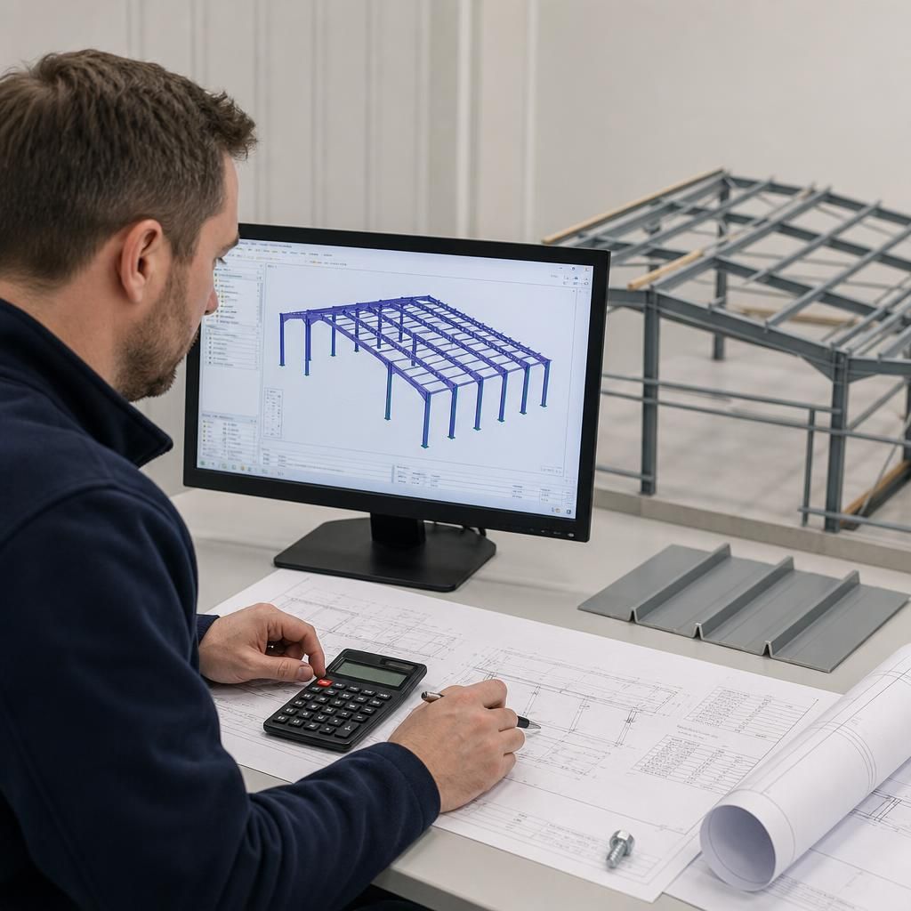
A suitable calculation package records the design assumptions, applied actions, load combinations, material properties, support conditions, fixing specification and utilisation results. Drawings should then identify the profile, thickness, span, laps, fastener types and spacing, support lines, edge zones and any restrictions on access or imposed loads. If the roof build-up or support arrangement changes during design or construction, the calculations and details should be reviewed rather than relying on the earlier assessment.
For a bespoke steel-framed building, this information is coordinated with the structural frame design and the cladding details. That approach helps maintain a continuous load path from the roof surface through the fixings and secondary steelwork into the primary frame. It also makes clear which components are designed to carry maintenance or equipment loads and which are not.
Calculated load capacity applies only when the installed roof matches the design assumptions and remains in suitable condition. For an existing roof, the assessment should therefore verify the actual sheet profile and thickness, support positions, fastener condition, corrosion, damage and any unauthorised alterations before relying on original drawings or published data.
Installation quality can also affect performance. Missing or incorrectly positioned fixings, poorly formed laps, unsupported sheet ends and damaged panels may reduce the resistance assumed in the calculations. Where site conditions differ from the design, the engineer may need to revise the model, specify remedial work or introduce additional support before accepting the roof for maintenance access or new imposed loads.
Discuss Your Roof Cladding System Design
Discuss your roof cladding system design with Buildings UK Ltd and provide the project information needed to review its structural requirements. This can help establish whether the proposed cladding, fixings and supporting steelwork are coordinated for the intended loads.