
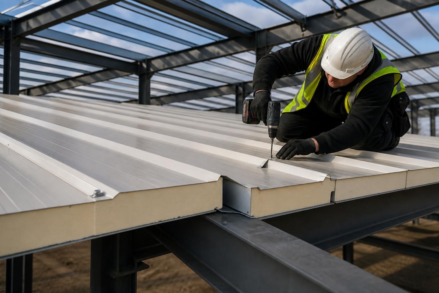
How are insulated roof panels fixed to steel frames?
Insulated roof panels are usually fixed to steel purlins using corrosion-resistant self-drilling screws with sealing washers, driven through the panel into the supporting steelwork. Side laps are secured with suitable stitching screws and sealed where required, while the fixing type, length, spacing and edge distances must be specified for the panel system, steel thickness, wind loads and roof layout.
Insulated roof panels are connected to a steel-framed building through the supporting purlins, with the fixing arrangement designed to transfer wind and other roof loads without compromising the panel’s weather seal or insulation. The exact detail depends on the panel profile, core construction, steel thickness, roof geometry and the manufacturer’s installation requirements.
Common fixing arrangements
- Through-fixing: a fastener passes through the panel and into the steel purlin. A sealing washer sits beneath the fastener head to close the penetration through the external sheet.
- Concealed fixing: some panel systems use an interlocking joint and concealed clips or brackets. The clip is attached to the purlin, after which the next panel engages with the joint. This can reduce exposed fixings, but the clip and joint must be compatible with the specified panel.
- Side-lap fixing: adjacent panels are secured at their longitudinal joint using suitable stitching screws or the joint detail specified for that system. Joint seals or gaskets may be required to maintain airtightness and weather resistance.
Before installation, the steelwork should be checked for line, level, spacing and adequate bearing. Purlins that are out of position can make the panel joints difficult to close and may place unintended stress on the sheets. The installer should also confirm the direction of laying, the position of the panel ends and the required eaves, verge, ridge and valley details before the first panel is fixed.
How the installation is normally carried out
- The first panel is positioned accurately at the nominated edge of the roof and supported across the designed purlin positions.
- It is temporarily held or restrained while the first permanent fixings are installed. Fixings should be placed in the locations permitted by the panel system rather than wherever the sheet appears most convenient to pierce.
- Further panels are placed with their side joints fully engaged. Joint seals, if specified, must remain continuous and free from dirt, gaps or folds.
- Fixings are installed progressively into the supporting steelwork, keeping the panel straight and avoiding distortion of the joint.
- Flashings, closures and trims are fitted at the roof perimeter and around openings. These components help close the profiled edges and direct water away from vulnerable joints.
The fastener must be long enough to pass through the panel assembly and develop the required connection in the purlin, while remaining suitable for the thickness and grade of the supporting steel. Self-drilling fasteners are commonly used where the substrate permits, but the drill point, thread form and corrosion protection should be selected for that particular steel section and environment. The washer material also matters: it needs to remain compatible with the external sheet and provide a durable seal.
Correct tightening is important. An under-tightened washer may not seal the penetration, whereas excessive torque can crush the panel face, deform the washer or damage the joint. Many systems require the washer to seat evenly without being forced deeply into the sheet. Installation should therefore follow the fastener and panel manufacturer’s guidance, using a controlled driver rather than relying on visual appearance alone.
Fixing positions and quantities are established from the design loads and the panel manufacturer’s tested performance. Wind uplift is often critical at corners, verges and roof edges, where local suction can be greater than across the main roof area. The design may therefore require a different arrangement in these zones. Openings, rooflights, raised kerbs, plant supports and service penetrations also need their own perimeter support and weathering details; they should not simply be cut through a panel without checking how the load path and seal will be maintained.
Care is needed to avoid thermal and corrosion problems at the connection. A metal fastener creates a local thermal bridge through the insulated envelope, so unnecessary additional penetrations should be avoided and the panel joint should remain properly closed. Cut edges, swarf and damaged coatings must be removed or treated in accordance with the system requirements, since trapped metal debris can stain the sheet or contribute to corrosion. Dissimilar materials should not be brought together without checking their compatibility.
At completion, the roof should be inspected for missing or poorly seated fixings, distorted washers, open side joints, damaged coatings, incomplete flashings and unsealed penetrations. The finished connection is satisfactory only when the structural attachment, panel joint, insulation continuity and external weathering detail work together. For this reason, fixing information should be coordinated with the steel-frame drawings and the panel supplier’s technical details before fabrication and installation.
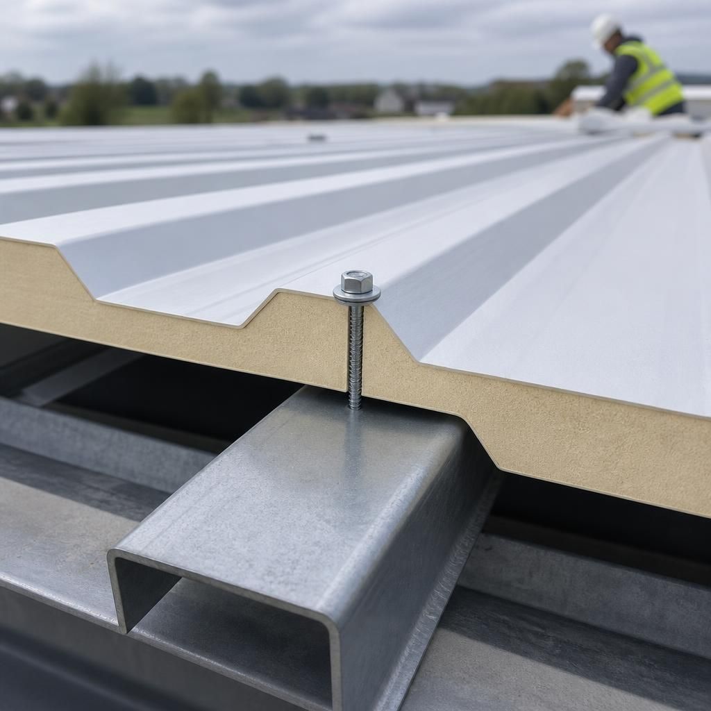
A crucial detail is the position of each fixing on the purlin flange. The screw should engage the supporting steel within the permitted edge distance and avoid the flange edge, where the connection may have less resistance to pull-out or tear-out. Panel ends must also sit fully over their designed supports; a fastener should not be relied upon to carry a panel across an unsupported gap.
This is particularly important where purlins are slender, closely spaced or interrupted around roof openings. The steel-frame drawings and panel layout should identify the available fixing zones before installation, so the screws connect with sound supporting steel rather than landing beside a flange, at a cut-out or in an unreinforced area.