
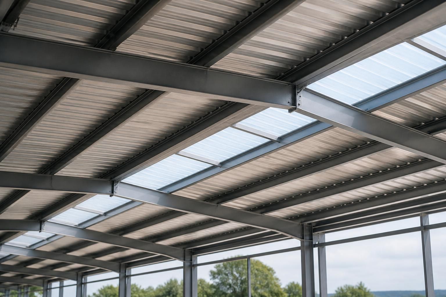
What support spacing is needed beneath metal roofing sheets?
There is no universal support spacing for metal roofing sheets: it must be determined from the sheet profile, gauge, span capacity and the loads acting on the roof. Purlin spacing should follow the manufacturer’s load-span tables and the project’s structural design, including wind, snow, maintenance and any imposed loads.
Support spacing beneath metal roofing sheets is the distance between the structural members that provide continuous bearing to the sheets. It must allow the sheet to transfer roof loads safely to the purlins or rails while limiting deflection, vibration and stress around the fixings.
The correct arrangement depends first on how the sheets span. In a typical pitched steel-framed building, sheets span from one purlin to the next, with the profile ribs providing stiffness between supports. The purlins must be positioned square to the sheet span and set out accurately so every required bearing line is available. Where sheets are laid over timber rafters, cold-formed rails or an existing structure, the same principle applies, but the supporting members must also be checked for their own strength and deflection.
- Sheet profile: deeper or more strongly formed profiles generally have greater spanning capability than shallow profiles, but the permitted spacing remains product-specific.
- Sheet thickness: a thicker gauge usually provides greater resistance to bending and local damage, although it does not remove the need to check the complete roof system.
- Roof loads: snow, wind suction, maintenance access, suspended items and any imposed loads can affect the required arrangement. Downward loading and wind uplift may govern different parts of the design.
- Sheet length and laps: end laps should occur over a suitable support rather than between supports. Additional fastening or closer support may be required at lap positions, depending on the system design.
- Roof edges and corners: wind actions are often more severe around perimeter and corner zones, so the support and fixing design may differ from that used in the central roof area.
- Roof construction: single-skin sheets, insulated built-up roofs and composite panels use different support arrangements. Liners, spacer systems, insulation and side-lap details must be compatible with the chosen roof build-up.
Spacing should be taken from the load-span information issued for the precise sheet profile and gauge. These tables normally identify permissible spans for particular loads and support conditions, together with limits for deflection and fixing requirements. They should not be applied to a visually similar profile or a different material without confirmation, because small changes in shape, steel thickness or coating can alter the result.
The design should also consider whether the sheets are simply supported or continuous over several purlins. A continuous sheet may behave differently from a sheet supported at two points, while an end bay, verge, eaves or ridge can introduce conditions that are not represented by a standard internal span. Any cantilevered overhang should be limited in accordance with the system design and should not be treated as ordinary span between purlins.
Purlin sizing and sheet support spacing are related but separate checks. A purlin may be strong enough in bending yet fail to meet the required deflection limit, move under wind uplift or twist under an eccentric load. Purlin cleats, laps, bracing and connections must therefore be assessed alongside the sheets. The supporting frame must also be installed to the specified line and level; excessive variation can leave part of a sheet unsupported or concentrate load at a single rib.
Fixings are part of the spacing design rather than an afterthought. Their type, position and frequency must suit the sheet material, support material, wind exposure and lap arrangement. Fixings should be placed in the locations specified for the profile, with washers seated correctly and without over-tightening. Poorly positioned or over-driven fixings can damage the sheet and reduce its resistance to wind uplift, even where the purlin spacing itself is adequate.
During installation, check that each purlin or rail is present beneath the intended fixing line, that end laps are fully supported and that sheets are not forced into position to compensate for inaccurate framing. Do not walk on unsupported sheet areas, and do not assume that a roof can carry stored materials or temporary access equipment unless those loads have been included in the design.
For a new steel-framed building, the support layout should be coordinated between the structural design, the sheet manufacturer’s data and the fabrication drawings before manufacture. For a replacement roof or refurbishment, the existing purlins should be inspected for corrosion, damage, spacing and capacity rather than reused automatically. Where the roof is unusual, heavily loaded or exposed to demanding wind conditions, a suitably qualified structural designer should confirm the arrangement before installation.
In practice, the appropriate spacing is the closest value that satisfies the sheet system, the supporting structure, the roof loads, the edge and lap details, and the installation requirements together. A generic spacing taken from another building is not a reliable basis for design.
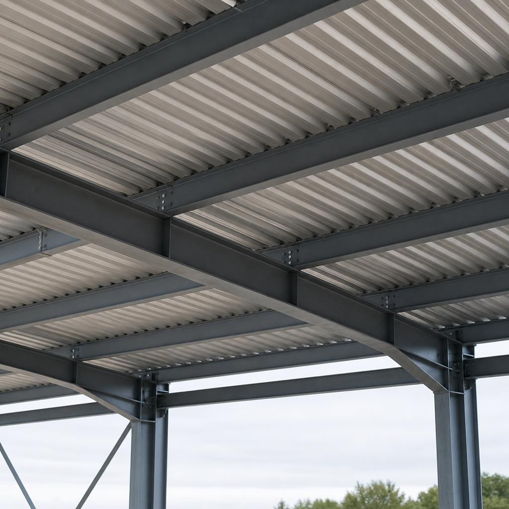
Roof openings need their own support arrangement because a rooflight, vent, access hatch or service penetration interrupts the normal load path between the metal roofing sheets and the purlins. The sheets should not be left spanning across an opening unless that arrangement is specifically covered by the roofing system design.
Openings are normally formed with framing around their perimeter so the cut sheet edges have suitable bearing and the loads can be transferred into the surrounding structure. This may involve trimmer members, altered purlin positions or additional support, depending on the opening and the roof build-up. The support layout should be agreed before the sheets are manufactured or cut, since moving a penetration on site can leave fixings, laps or sheet ends without the intended support.
Roof-mounted equipment also needs consideration. Items such as ductwork, plant, solar equipment or suspended services should be supported from the structural frame rather than relying on the roofing sheets, unless the system has been specifically designed for that load. Coordinating these requirements with the purlin layout helps preserve the intended support spacing and prevents concentrated loads being introduced into unsupported sheet areas.