
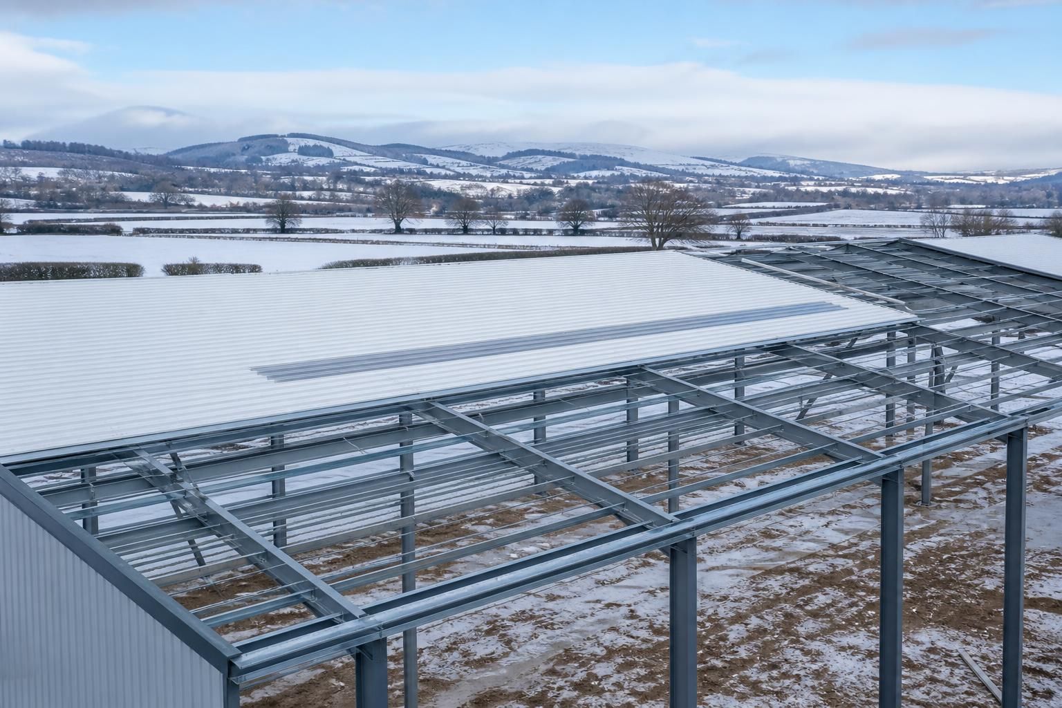
What roof loads should a steel frame building be designed to withstand?
A steel frame building roof should be designed for its permanent construction loads, snow loading, wind pressure and uplift, maintenance access, and any planned services or equipment. The structural engineer assesses these actions against the building’s location, dimensions, roof form and intended use to establish compliant members, connections and stability requirements.
Roof loads are the forces and weights transferred through the roof covering, purlins, rafters, columns, connections and foundations. A steel frame building must be checked for both gravity loads acting downwards and environmental actions that can create pressure, suction, sliding or uneven loading. The design is based on the building’s location, geometry, use, materials and any equipment intended to remain on the roof.
Permanent loads are the loads that remain in place throughout the building’s life. They include the steel roof members, roof sheets or panels, insulation, liner systems, rooflights, gutters, flashings and other fixed components. The designer also allows for secondary steelwork and any permanently attached items. Although these loads are generally predictable, the specification should be sufficiently developed before design calculations are completed, because changing to a heavier roof build-up can alter the required purlin and rafter sizes.
Snow loading is assessed using the building’s site location, roof shape, pitch and exposure. The design must consider not only an evenly distributed layer of snow, but also situations where snow accumulates more heavily in one area. Drifting can occur beside parapets, changes in roof level, roof obstructions and adjoining structures. An uneven snow pattern can produce greater bending and twisting in individual rafters than a uniform load, so it should be included where the roof geometry makes it relevant.
Wind loading acts differently from gravity loading. Wind can press against the roof and walls, but it can also create suction that attempts to lift the roof covering and supporting steelwork. Edge and corner zones are often subject to higher local pressures than the central roof area. Open-sided buildings, large door openings and buildings with significant ventilation can also have different internal pressures from enclosed structures. The cladding fixings, purlins, rafters, bracing, holding-down bolts and foundations must form a continuous load path for these forces.
Maintenance access should be considered even where the roof is not intended for regular occupation. A person carrying tools, temporary access equipment or replacement materials can create a localised load rather than a load spread evenly across the entire roof. Rooflights and fragile areas require particular attention, as their ability to support maintenance activity may differ from that of the surrounding cladding. Safe access arrangements and any designated walkways should be coordinated with the structural design.
Planned services and equipment can introduce concentrated loads and should be identified at the design stage. Examples include ventilation units, suspended services, extraction systems, lighting, sprinkler pipework, solar panels and lifting or handling equipment attached to the structure. Their weight, support arrangement, vibration and maintenance requirements may affect the design. A point load applied between purlins is not equivalent to the same weight distributed across the roof, and may require local strengthening or additional support.
For agricultural and industrial buildings, the intended use may create further design considerations. Suspended ceilings, conveyors, feed or extraction systems, storage arrangements and internal handling equipment can transfer forces into the roof frame. Where a building may be altered later, such as by adding services or roof-mounted equipment, that possibility should be stated before the steelwork is sized. Designing for an undefined future load is not a substitute for specifying the actual load and its support position.
The structural engineer checks how each load is transferred through the roof system. Roof sheets pass loads to purlins; purlins transfer them to rafters or trusses; rafters pass forces through connections to columns; and the columns and foundations resist the resulting vertical and horizontal actions. Roof-plane bracing, vertical bracing and rigid connections may be needed to control sway and transmit wind forces. Connections are checked for the forces generated by the load cases, rather than being treated as separate from the main frame design.
Load combinations are used because the most demanding condition may not involve every action at its maximum value at the same time. For example, a gravity-dominated case may combine permanent loads with snow or maintenance loading, while an uplift case may be governed by wind with stabilising dead load reduced according to the relevant design rules. Unbalanced snow, wind from different directions and local effects are considered where applicable. The governing combination can vary between roof sheets, purlins, rafters, columns, connections and foundations.
Design calculations should follow the applicable British and European structural design standards, including the relevant UK National Annexes, together with project requirements and Building Regulations where applicable. The design information normally records the site parameters, roof construction, imposed loads, environmental actions, load combinations, member checks, connection design and foundation reactions. Planning elevation drawings show the external form, while fabrication information must reflect the member sizes, bracing and connection requirements established by the structural design.
Before requesting or approving a design, provide the designer with the site location, building dimensions, roof profile, cladding build-up, rooflight arrangement, openings, internal use and all known roof-mounted or suspended equipment. Also identify whether the building is enclosed, open-sided or likely to be modified. These details allow the roof loads to be assessed for the actual building rather than relying on generic assumptions. A later change to the roof covering, equipment or use should be referred back to the designer, because it may require a revised check of the steel frame and its connections.
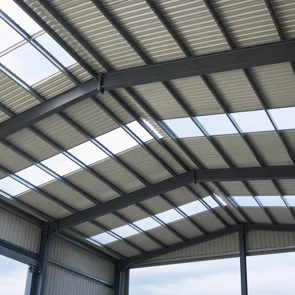
A steel frame roof must be checked for serviceability as well as strength. This means assessing whether load-related deflection, movement or vibration could affect roof sheets, rooflights, drainage falls, doors, partitions or attached equipment, even when the steel members remain within their strength limits.
Serviceability checks consider the relevant load condition and the sensitivity of the roof build-up. Excessive movement can damage finishes, disturb cladding fixings or allow water to collect on low-pitched areas. The required limits depend on the structural arrangement, materials, spans and project requirements, so they should be agreed as part of the engineering design rather than assumed from member size alone.