
What roof loads must metal roof panels accommodate?
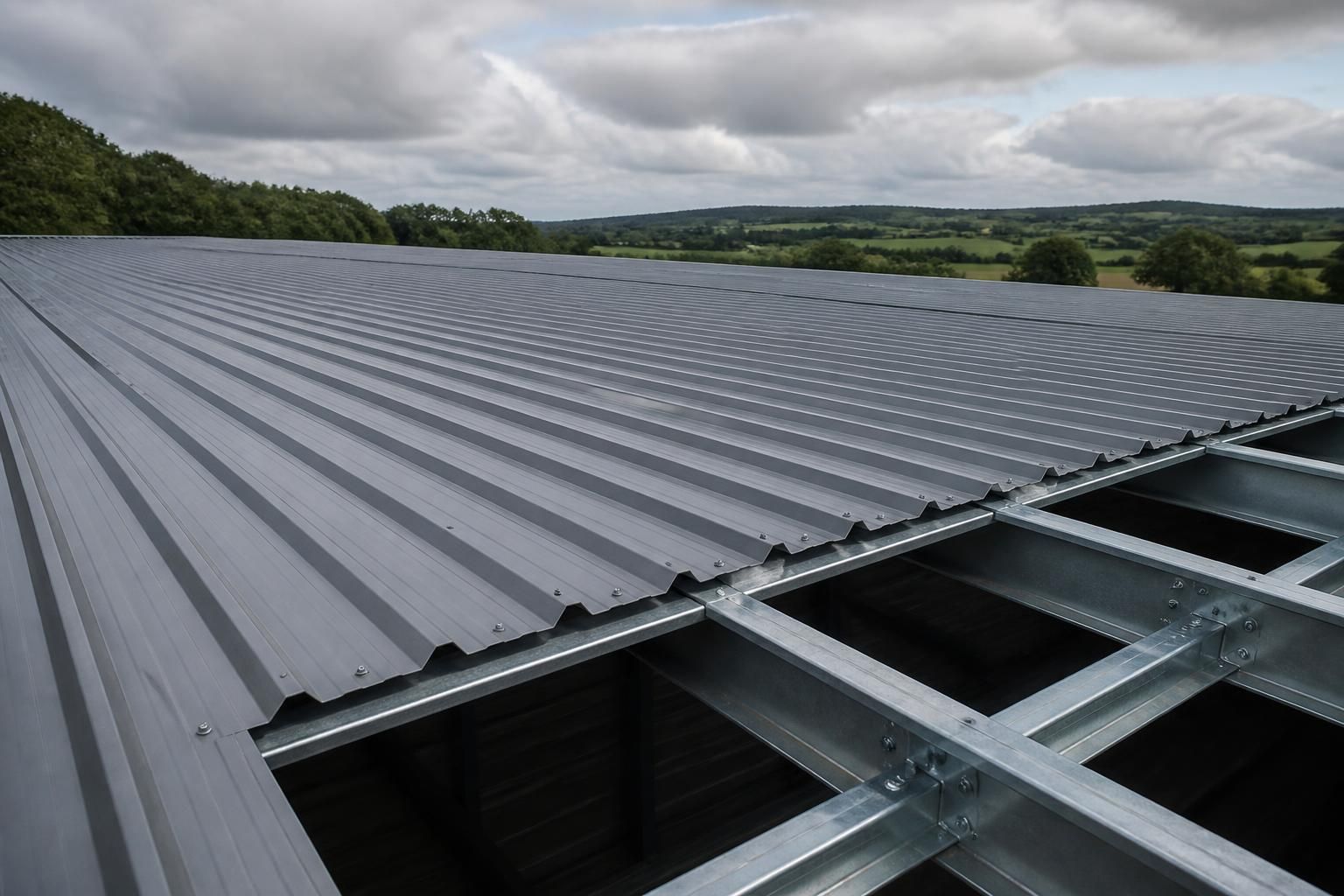
Metal roof panels must accommodate their own weight, imposed maintenance loads, snow loading, wind pressure and wind uplift, together with any loads transferred by roof-mounted equipment or services. These actions must be assessed in combination with the panel span, profile, fixings, support spacing and the capacity of the underlying steel frame.
Metal roof panels are designed as part of a complete roof system, not as isolated sheets. The assessment must establish the loads acting on the panels, convert them into reactions at the supports and fixings, and confirm that the panels, secondary steelwork, connections and primary frame can resist the resulting forces without unacceptable deflection or damage.
Permanent actions include the panel or sheet itself, insulation, liners, vapour-control layers, trims, rooflights, flashings and any permanently attached services. Although these components are relatively light compared with many traditional roof coverings, their combined weight is transferred through the panel profile into purlins or other supporting members. The design should use the actual proposed build-up rather than an assumed panel weight, particularly where extra insulation, acoustic treatments or suspended items are included.
Snow loading is assessed for the building’s location, roof geometry and exposure. A uniformly distributed layer is only one possible arrangement. Snow can drift at changes in roof level, beside parapets, near taller adjoining buildings and around obstructions such as plant or rooflights. Localised accumulation may therefore create a more demanding condition than an even covering. The designer also considers whether snow is likely to slide from one roof surface onto a lower area, where the receiving panels and supports may require additional capacity.
Wind actions vary across the roof. Pressure may act towards the building, while suction can lift the panels away from their supports. Edge zones, corners and areas around roof penetrations commonly experience higher local effects than the central roof area. Wind design must consequently consider the building’s dimensions, shape, position, surrounding terrain and the size and location of openings. A roof that performs adequately in the middle of its span may still require stronger edge fixings or closer support spacing at its perimeter.
Wind uplift is resisted through the complete load path: the panel, fastener, washer, rail or purlin, connection and steel frame must all remain secure. Failure can occur at the fixing, through pull-out from the supporting steel, by tearing around the fastener or by local deformation of the panel. Fixing arrangements should therefore be checked for both the number and location of fasteners and the capacity of the supporting material. The strongest panel profile cannot compensate for an inadequate connection.
Maintenance loading accounts for people and equipment needed for inspection, cleaning and routine roof work. The applicable load is not treated as a general invitation to use the roof for storage. Where access is required, the design should identify safe access routes, walkways, working platforms and any areas needing additional support. Concentrated loads from a person’s foot, a ladder or temporary equipment can be more critical locally than the same load spread over a wide area.
Roof-mounted equipment creates further concentrated actions. Air-conditioning units, extraction equipment, solar arrays, ductwork, tanks and service supports may impose vertical weight, horizontal forces and local reactions. Some equipment can also introduce vibration or require penetrations that interrupt the panel’s continuity. These loads should be identified before the roof is designed so that dedicated support steelwork can be provided where necessary, rather than relying on the panel skin to carry an unsuitable point load.
Serviceability is as important as ultimate strength. A panel may theoretically resist a failure load yet still be unsuitable if it deflects excessively, causes water to collect, damages laps or allows fixings and seals to loosen. Deflection limits, vibration, ponding risk, drainage falls and the performance of side and end laps should be considered alongside strength. Repeated movement under changing wind or temperature conditions can also affect seals and connections over the building’s service life.
Load combinations are then applied so that the roof is checked under realistic concurrent actions rather than each action in isolation. The governing combination may differ between panel strength, fixing resistance, purlin bending, frame stability and serviceability. Snow may govern downward loading, whereas wind suction may govern fastener spacing and edge details. The design should also account for construction-stage conditions if panels are temporarily stacked or subjected to access loads before the complete roof build-up is installed.
For a steel-framed building, the assessment should follow the load path from the roof covering into the secondary steelwork and then through the frame and foundations. Buildings UK’s bespoke design packages include planning elevation drawings and isometric fabrication blueprints, which help coordinate the roof arrangement with the supporting steelwork. The required information should include the panel type and span, support spacing, roof build-up, openings, access provisions, equipment locations and the relevant site design conditions before manufacture and installation details are finalised.
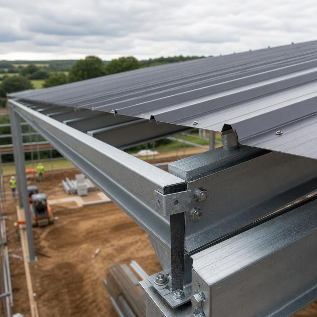
The load capacity stated for a metal roof panel is conditional on how the panel is supported and fixed. Published load tables or design information normally relate to a particular profile, material thickness, span arrangement, lap detail and fixing pattern, so a value should not be applied to a different roof configuration without checking the assumptions.
Particular care is needed where panels are continuous over more than one support, joined at end laps or interrupted by cut-outs. Continuity may change how forces are distributed, while unsupported edges and altered laps can reduce local resistance. The design review should therefore compare the proposed panel arrangement with the evidence or calculations for the selected system, including the intended support conditions and fixing details. This prevents a nominal panel capacity from being mistaken for the capacity of the completed roof assembly.