
What site details are needed to specify a steel building kit?
To specify a steel building kit, provide the required length, width, eaves height, roof profile and intended use, together with information about the site and its constraints. Ground conditions, levels, access for delivery and erection, planning requirements, openings, insulation and any loading requirements will help determine the frame design and building specification.
A steel building kit should be specified from verified site information, not dimensions alone. The design team needs enough detail to understand the site’s position, levels, ground, services, boundaries and surrounding constraints so that the frame, foundations, cladding and connection details can be developed correctly.
Provide the site location and orientation. The full address, postcode, site plan and a north point help establish the building’s position and exposure. Location can affect the structural design because wind conditions, snow loading, coastal exposure and the surrounding terrain vary between sites. The proposed building should also be shown in relation to boundaries, roads, existing buildings and any planned future development.
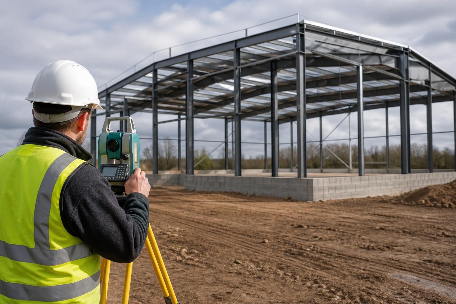
A measured survey is important where the ground is not level. A topographical survey can show contours, spot levels, retaining features, embankments and the relationship between the proposed building and nearby structures. It should identify a recognised datum and make clear whether levels refer to existing ground, a finished floor or another reference point. Accurate levels are particularly useful when preparing foundation details, setting finished floor heights and coordinating drainage.
Ground information should be supplied before foundation design is finalised. Useful information includes:
- soil type and any available ground investigation report;
- the presence of made-up ground, infill, rock or previously disturbed areas;
- groundwater, springs or a history of flooding;
- contamination or unusual ground conditions;
- existing foundations, hardstandings or slabs that may remain in place; and
- any known restrictions on excavation or piling.
A steel frame may be relatively light compared with some other forms of construction, but its reactions still need to transfer safely into the ground. Guessing the ground conditions can lead to unsuitable foundation assumptions, additional design work or changes once excavation begins.
Record buried and overhead services. Electricity, gas, water, telecommunications, drainage runs and overhead cables should be marked on a site plan where their positions are known. Service searches, utility drawings and trial holes may be required to verify uncertain routes. This information helps avoid clashes with foundations, holding-down bolts, drainage and construction activities.
Show legal and physical constraints. The specification should identify boundary lines, rights of way, easements, shared access, nearby property, trees, watercourses and any structures that must remain. A building that appears to fit on a plan may require changes if foundation pads cross a boundary, eaves project into a restricted area or construction affects a protected feature.
Include the information attached to the planning position. The design team may need the approved site plan, planning drawings, decision notice and any conditions that affect materials, height, appearance, drainage, landscaping or the building’s position. Where planning is still being considered, constraints such as proximity to dwellings, designated sites, heritage assets and local landscape requirements should be identified at the outset rather than treated as a later alteration.
Explain how the building will connect to the site. Details may be needed for the proposed finished floor, thresholds, apron, drainage, gutters, downpipes, service penetrations and interfaces with existing buildings. If the kit will sit on a concrete slab, provide any available slab drawings, reinforcement information, dimensions, construction date and evidence of its condition. The frame design should not assume that an existing slab is suitable for new steelwork without confirmation.
Supply photographs and a simple site plan. Photographs should cover the proposed position from several directions and show adjoining buildings, ground changes, overhead obstructions, access points and nearby services. Marking each photograph on a plan makes it easier to relate visual information to the design. Aerial imagery can provide context, but it should not replace a measured survey or utility information.
For an agricultural, industrial or equestrian project, also note any operational restrictions that affect the arrangement of the building. These can include livestock areas, machinery routes, hygiene zones, grain or feed storage, hazardous materials, ventilation requirements, wash-down areas and separation from existing operations. Such information helps coordinate the steelwork with the building’s eventual use without relying on assumptions.
Before the kit is released for manufacture, check that the site information agrees with the latest drawings. In particular, confirm the building position, finished floor level, foundation arrangement, service routes and connection points. If a survey, planning condition or ground investigation later changes one of these items, the steelwork may need to be redesigned before fabrication. A complete information pack therefore reduces uncertainty and provides a sound basis for the fabrication drawings and installation details.
Site details must include any loads or equipment that will be supported by the steel building, not just the building’s external dimensions. These requirements can alter the frame size, roof members, bracing, foundations and connection details, so they should be identified before the kit is designed.
- crane beams, hoists or lifting equipment;
- mezzanine floors, storage decks or internal platforms;
- racking, conveyors, machinery or fixed processing equipment;
- suspended services, tanks, ventilation systems or lighting;
- roof-mounted equipment, solar panels or maintenance access systems; and
- internal partitions or doors that may require additional framing.
For each item, provide its location, dimensions, weight and method of support where known. Also state whether loads are permanent, movable or subject to impact and vibration. A clear equipment layout allows the steel frame to be coordinated with the intended use rather than requiring later alterations to accommodate unsupported assumptions.