

How should aircraft hangar floor loading be specified?
Specify aircraft hangar floor loading from the aircraft’s maximum operating weight, wheel or landing-gear arrangement, individual wheel loads and any concentrated loads from jacks, stands or maintenance equipment. These design loads should then inform the reinforced concrete slab, sub-base, joints and ground conditions, with the final specification verified by a structural engineer.
Aircraft hangar floor loading should be specified as a complete set of structural and operational design criteria, rather than as a single maximum weight. The specification needs to show how the floor will be used, how loads reach the ground, how often they occur and what performance the finished surface must provide.
Begin with the operational brief. Identify the aircraft types and configurations the hangar is intended to accommodate, together with the way they will be moved, parked, maintained and stored. A floor used only for storage has different demands from one used for frequent towing, refuelling, component removal or heavy maintenance. The brief should also identify non-aircraft loads, such as tool cabinets, mobile access equipment, lifting equipment, parts storage, fuel-handling equipment and service vehicles.
Do not base the design solely on an average aircraft condition. The engineer should assess the most demanding credible arrangement, including an aircraft positioned unevenly, equipment parked close to a slab edge and loads applied where the supporting ground or joints provide less favourable support. If the hangar may be adapted for a larger aircraft or a different maintenance function later, that potential use should be recorded before the slab is designed.
Define the load cases and load path. The specification should distinguish between:
- permanent loads, such as fixed equipment, partitions and stored items;
- moving loads from aircraft, tugs, forklifts and other vehicles;
- localised maintenance or lifting loads;
- repeated traffic, which can affect surface wear and joint performance; and
- accidental or abnormal conditions that the project engineer considers relevant.
Each load must be considered through its complete path into the ground. This includes the contact area at the tyre or support, the local response of the concrete, the reinforcement, the formation and the sub-base. A heavy load spread over a large area may be less demanding locally than a smaller load applied through a narrow support. Loads close to slab edges, construction joints or penetrations can also produce different stresses from loads applied at the centre of an uninterrupted panel.
Account for movement and impact. A stationary aircraft and the same aircraft being towed do not necessarily impose identical design effects. Turning, braking, acceleration, uneven surfaces and crossing joints can introduce horizontal forces and short-duration effects. Jacks, trestles and maintenance supports may create highly localised reactions, particularly while an aircraft is being raised or supported during inspection. The design team should establish which of these conditions are permitted and whether special hardstanding, support points or operating restrictions are needed.
Coordinate the floor with the building layout. Hangar doors, tracks, thresholds, drainage channels, inspection pits, service trenches and utility penetrations should be shown on the floor-loading drawings. These features interrupt the load path and may require local thickening, edge reinforcement or a separate structural detail. Door thresholds are particularly important because aircraft and vehicles must cross them without creating an abrupt change in level or a vulnerable slab edge.
Joint locations should be coordinated with the expected movement routes and support positions. A joint directly beneath a frequently used wheel path or maintenance support may receive more demanding repeated loading than a joint in a low-traffic area. Joint type, load transfer, sealant and protection against fluid ingress should therefore be stated in the design information rather than left to site interpretation.
Use the ground investigation to set the slab design. A ground-bearing floor depends on the formation and sub-base as well as the concrete. The specification should identify the expected bearing conditions, compaction requirements, potential for settlement, groundwater considerations and any need for ground improvement. Where the ground is variable or settlement cannot be controlled reliably, the engineer may need to consider an alternative floor construction or a different support strategy. Concrete thickness and reinforcement cannot compensate for every weakness in the underlying ground.
Specify service performance as well as structural capacity. The floor may need to resist abrasion from aircraft tyres and maintenance traffic, tolerate oils or other aviation-related fluids, and provide a suitable slip-resistant finish without creating obstacles for towing. Surface regularity and level tolerances matter where aircraft are moved on small wheels, where equipment must be positioned accurately or where doors and tracks meet the floor. Drainage falls, channels and sumps should be designed alongside the loading requirements so that water or spilled fluids do not weaken the sub-base or create operational hazards.
Concrete strength, reinforcement, curing, surface finish and protection should be selected for the actual environment and loading regime. The specification should also state how cracking, shrinkage and joint movement are to be managed. These are not substitutes for structural design, but they influence whether the completed floor continues to perform under repeated use.
The final design information should include a floor plan showing load zones, joint positions, penetrations, thresholds and any areas requiring enhanced construction. It should record the aircraft and equipment assumptions, load combinations, ground criteria, construction tolerances and any operational limitations. A structural engineer should verify the calculations and details against the project brief and the applicable UK design standards before construction, particularly where the hangar has heavy maintenance activities, unusual support arrangements or provision for future aircraft.
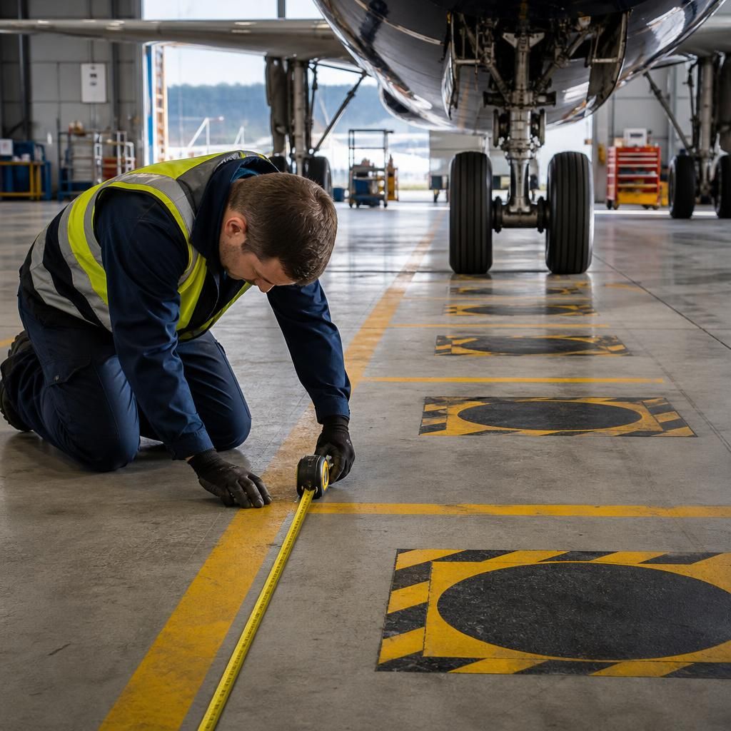
Aircraft hangar floor loading should distinguish the aircraft’s total operating weight from the pressure and contact area applied at each wheel. The specification should state the design basis for tyre or wheel contact, including the applicable aircraft loading condition, landing-gear arrangement, wheel spacing and any available tyre-pressure data. Maximum aircraft weight alone does not show how intensely the slab will be loaded locally.
Where tyre data may vary, the engineer should identify the assumed contact footprint and the limits that apply to future aircraft or replacement equipment. Smaller, harder wheels on maintenance equipment can create a more severe local demand than aircraft tyres, even where the equipment has a lower overall weight. Forklifts, dollies and access equipment should therefore be assessed using their own wheel or caster reactions rather than being treated as a general allowance.
Presenting these assumptions on a load schedule or plan helps prevent the floor being used beyond its design basis. It should identify the permitted aircraft and equipment categories, the governing local reactions and any restrictions on alternative wheels, concentrated supports or future changes in use.