
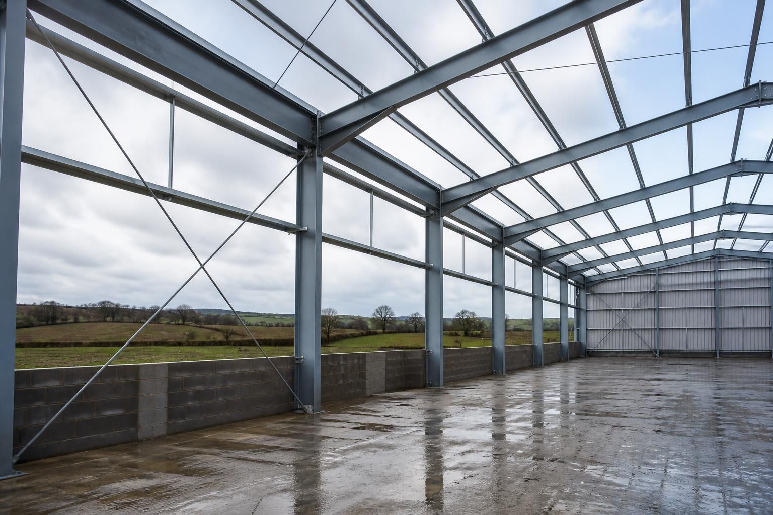
What role does bracing play in portal frame buildings?
Bracing stabilises a portal frame building by transferring wind and other horizontal forces through the steelwork and into the foundations. It helps prevent unwanted movement, keeps the frame aligned during construction and supports the building’s overall structural integrity.
Bracing in a portal frame building is the secondary steelwork and restraint system that controls buckling, limits distortion and helps the primary columns and rafters perform as designed. It is not a single component: the arrangement normally combines roof-plane bracing, vertical wall bracing, eaves members, purlins, side rails and local restraints.
Roof bracing is usually positioned within selected bays between portal frames. Diagonal members create a stable plane across the roof and provide restraint to the frame during loading and erection. Eaves struts and associated connections help maintain the relationship between the roof and the side walls. The roof sheeting may contribute some restraint in a designed system, but this cannot be assumed without suitable specification, fixings and engineering verification.
Vertical bracing is installed in selected wall bays to provide longitudinal stability along the length of the building. Depending on the design, it may use tension-only rods, angles or other steel members capable of resisting the required actions. Bracing bays are connected to the primary frame and to the foundations through designed connections, so the forces have a continuous, defined route through the structure.
Bracing also provides restraint against member buckling. Purlins and side rails can restrain parts of the rafters and columns, particularly their compression flanges, but their size, spacing and connections must be designed for that function. A purlin should not automatically be regarded as a complete substitute for a dedicated brace. The required arrangement depends on the steel section, span, frame spacing, applied loads and the restraint offered by the building envelope.
The design of a bracing system considers more than ordinary wind loading. The engineer may need to assess actions arising from the building’s height and proportions, roof and wall cladding, imposed loads, suspended equipment, crane operation, temperature movement and the way the structure is erected. Agricultural and industrial buildings can have different requirements because of their internal use, stored materials, machinery and openings.
- Building geometry: length, width, eaves height, roof pitch and portal frame spacing influence the number and position of braced bays.
- Openings: roller doors, loading doors and large glazed areas can interrupt a conventional wall-bracing arrangement. Bracing may need to be relocated or replaced with a designed alternative around the opening.
- Cladding and internal fit-out: the presence, fixing and continuity of cladding, partitions, cranes or services can affect the restraints available to the steelwork.
- Connections: gusset plates, cleats, bolts and welds must be designed for the forces in the bracing members, not merely for the weight of the components.
- Movement: the arrangement must provide restraint where required without preventing intended thermal or structural movement.
Temporary bracing is also important during construction. A portal frame is not necessarily stable as soon as one frame has been erected. Temporary members and an agreed erection sequence may be needed until enough frames, purlins, side rails and permanent bracing are connected. These temporary measures should remain in place until the permanent stability system is complete and checked.
Bracing must remain continuous and effective after construction. Removing a brace to create space for a service, cutting around an opening or altering a connection can change the behaviour of the whole frame. Any proposed alteration should therefore be referred to the structural designer, particularly where it affects a braced bay, eaves member, purlin or side rail.
For a bespoke portal frame, the bracing layout is developed alongside the frame analysis, foundation design, openings and cladding specification. The design drawings should identify the location and type of each bracing member, its connections and any requirements for temporary erection stability. This coordinated approach helps ensure that the completed building has a deliberate stability system rather than relying on components that were not designed to act as bracing.
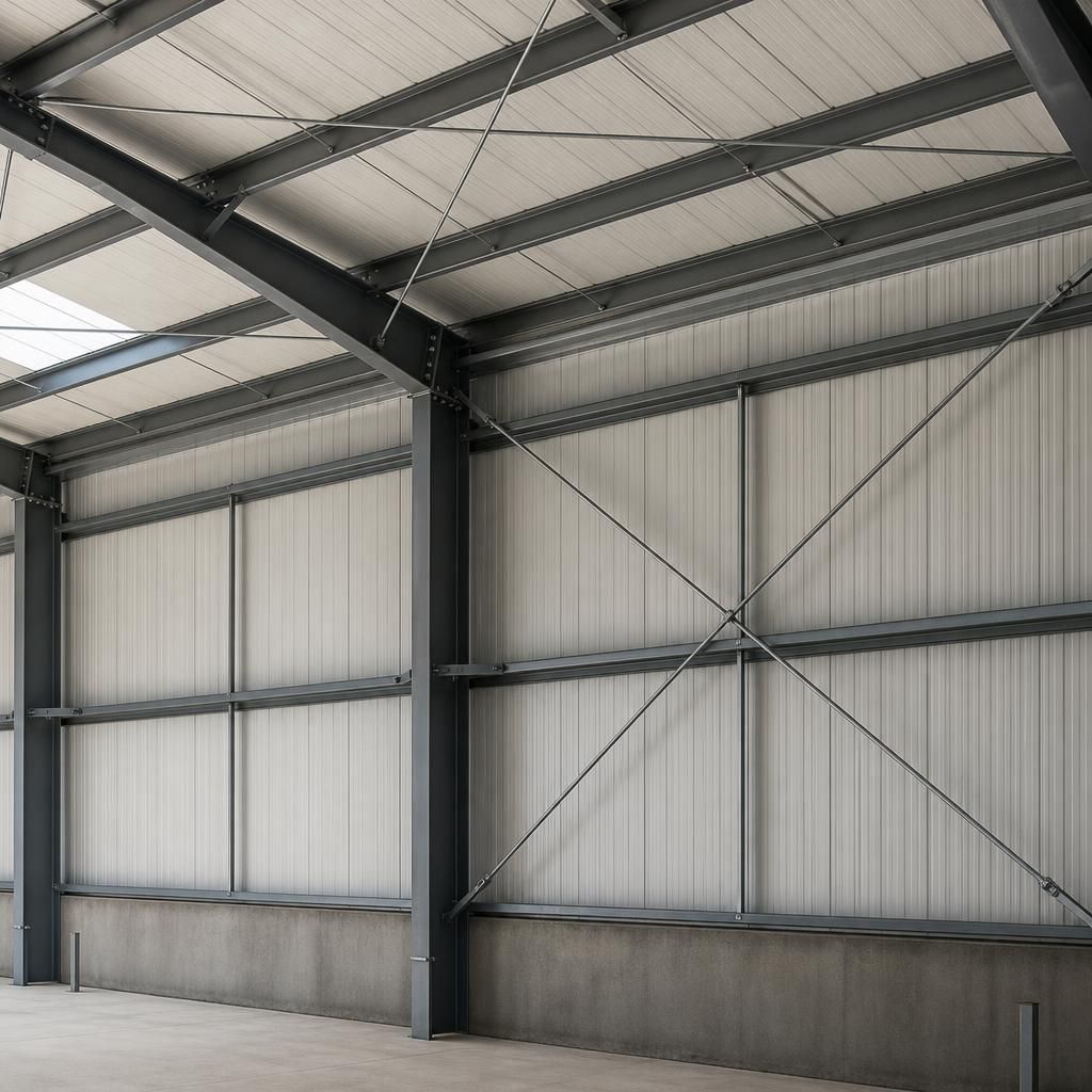
Bracing must also be protected from damage during the building’s working life. In agricultural and industrial buildings, forklifts, telehandlers, stored materials, livestock and suspended equipment can strike or overload accessible members. A bent rod, distorted angle or loosened connection can reduce the effectiveness of the stability system even when the main portal frames appear undamaged.
Braced bays should therefore be considered when planning vehicle routes, storage areas, partitions and internal machinery. Members and connections should remain accessible for inspection where practical, while vulnerable areas may require physical protection. Any damaged or altered bracing should be assessed by the structural designer before it is removed, straightened or replaced, because its effect extends beyond the individual member.
Discuss your portal frame bracing requirements
Discuss your portal frame bracing requirements with Buildings UK Ltd to establish a suitable stability strategy for your proposed building. Their bespoke design service can coordinate the bracing arrangement with the wider structural design and provide the relevant technical drawings.