
How are steel frame building connections designed?
Steel frame building connections are designed by analysing how loads transfer between beams, columns, bracing and foundations, then specifying suitable bolted or welded joints for the resulting forces. Structural calculations establish the connection sizes, materials and detailing, which are then translated into fabrication drawings and checked for safe assembly on site.
A steel frame connection is designed as a force-transfer detail: it must carry the required axial force, shear, bending moment or combination of actions from one member into another without exceeding the resistance of the bolts, welds, plates, cleats, end plates or supporting steel. The detail must also remain practical to fabricate, transport, inspect and assemble.
Design starts by identifying the forces arriving at each joint. These may come from permanent loads such as the frame, roof coverings and cladding; variable loads such as imposed agricultural or industrial use; wind pressure and suction; snow; crane actions; and forces generated by bracing or temperature movement. The design team considers the relevant load combinations rather than checking every action in isolation. A connection at an eaves, ridge, column base or bracing intersection can therefore require a different arrangement even when the connected members appear similar.
The joint geometry is selected to suit the way the frame behaves. Common arrangements include:
- Beam-to-column connections: these may transfer shear alone or may also resist bending and axial force, depending on whether the frame is designed as simply supported or moment-resisting.
- Column bases: base plates and holding-down bolts transfer compression, shear and sometimes uplift or overturning into the foundations.
- Bracing connections: gusset plates, cleats and bolts must accommodate forces that can reverse direction under changing wind actions.
- Rafter and ridge connections: these are shaped to transmit the forces in the roof members while maintaining the required frame geometry.
- Secondary steel connections: purlins, side rails and eaves members are connected so that they support cladding and restrain the primary frame where intended.
Engineers then check the resistance of every component in the load path. For a bolted joint, this can include bolt shear, bolt tension, combined shear and tension, bearing of the bolt against the connected plate, tearing at a plate edge, failure across a reduced net section and block tearing around a group of holes. Plates may also need checking for bending, buckling or local yielding. These checks are important because a bolt can have adequate strength while the thinner plate around it does not.
Welded joints are assessed differently. The design considers the effective throat of the weld, its length, its orientation and the forces acting through it. The parent steel and the heat-affected region must also be suitable for the proposed weld and fabrication method. Weld access, distortion, inspection requirements and the sequence of fabrication can affect the final detail, so a theoretically adequate weld is not necessarily an appropriate construction detail.
Connection stiffness is considered as well as strength. A joint classified as nominally pinned should not unintentionally restrain rotation and attract significant moment. Conversely, a rigid or semi-rigid joint must have sufficient rotational stiffness and resistance to perform the role assumed in the frame analysis. Where the line of action does not pass through the intended centre of resistance, the resulting eccentricity creates additional moment that must be included in the design.
Steel connection design in the UK commonly follows the relevant structural steelwork provisions of the Eurocodes and their UK National Annexes, including the rules for joints in BS EN 1993-1-8. The design also needs to align with the requirements for execution, tolerances, materials, welding and inspection. The governing project specification may set additional requirements for corrosion protection, fire performance, finish or inspection.
Durability is built into the connection detail rather than added afterwards. Designers allow for the specified protective coating, avoid unnecessary water traps, provide suitable access for preparation and coating, and consider whether dissimilar materials could cause corrosion. In exposed agricultural or industrial environments, the connection may need particular attention to moisture, condensation, chemicals, dust and trapped debris. Fire protection systems can also require clearances, compatible coatings or changes to the shape of the detail.
Fabrication and erection requirements influence the choice between bolts and welds. Shop welding can produce controlled, repeatable joints, while bolting is often useful where members must be assembled and adjusted on site. The design must allow tools to reach the bolts, provide enough clearance for tightening, and avoid clashes with purlins, cladding, bracing or other services. Bolt holes, edge distances, bolt spacing and access zones are set out so that the joint can be assembled without forcing members into position.
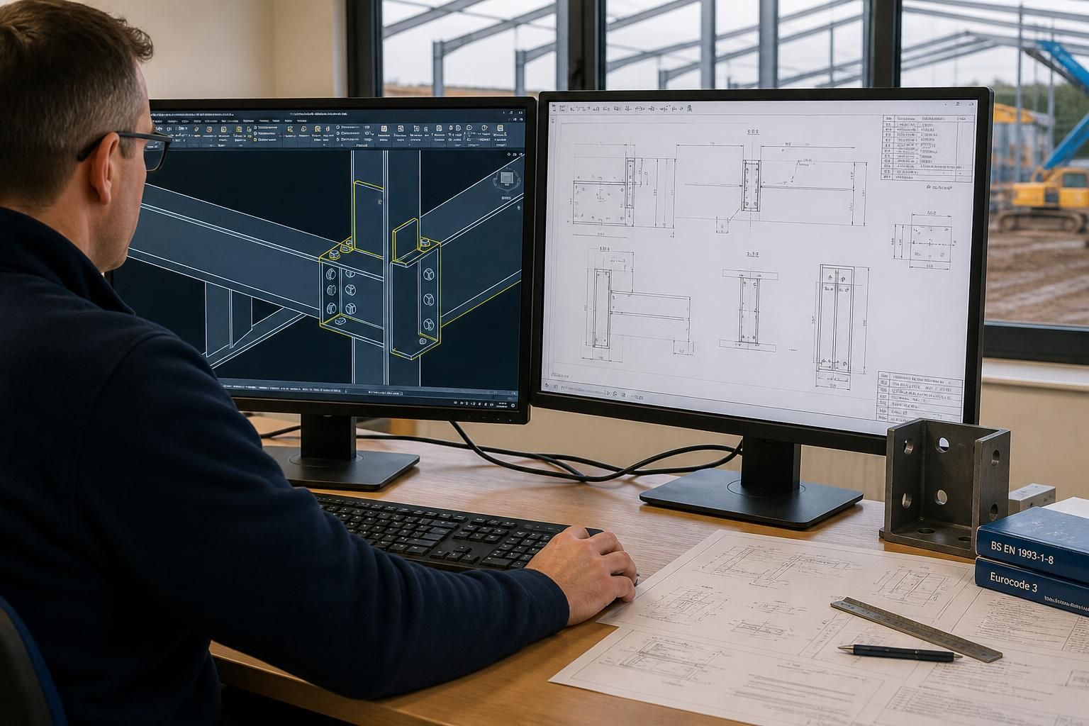
Design information is converted into detailed fabrication drawings showing member marks, plate thicknesses, steel grades, bolt sizes and grades, hole arrangements, weld symbols, finishes and any site-bolted interfaces. Details may also identify temporary stability requirements, erection marks and permitted tolerances. The drawings should agree with the structural model, the general arrangement drawings and the foundation design; discrepancies between these documents need resolving before manufacture.
Before a connection is released for fabrication, it is checked for design assumptions, dimensions, load cases, material specifications and buildability. During manufacture and erection, inspection verifies items such as member position, bolt installation, weld quality, plate fit-up and coating condition in accordance with the project requirements. This final verification matters because a correctly calculated connection can still perform poorly if it is altered, assembled incorrectly or prevented from achieving the movement assumed in the design.
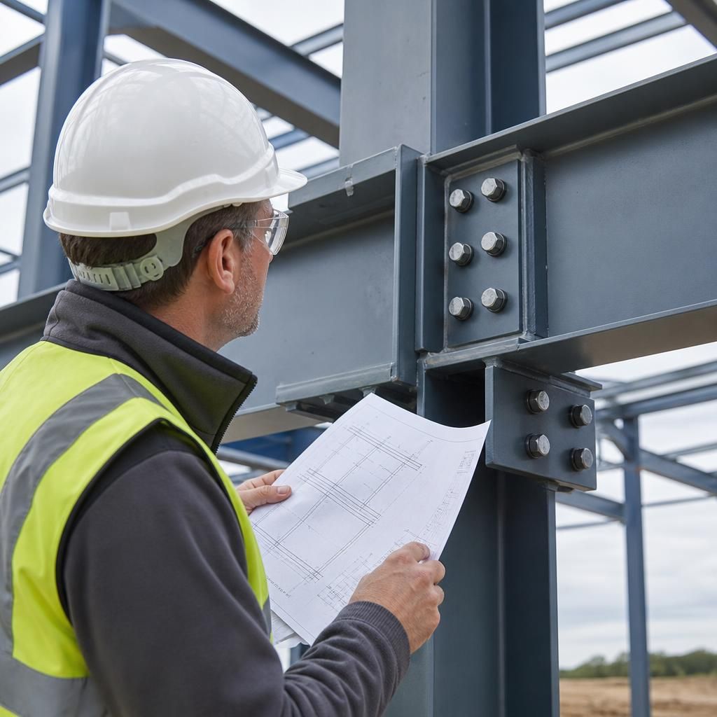
Connection design also determines whether a bolted joint may accommodate limited slip or must resist it at the interface. Bearing-type joints transfer force through contact between the bolt and the hole, while preloaded friction-grip joints use controlled bolt tension to clamp the plates and limit movement between them. The appropriate arrangement depends on serviceability requirements, fatigue, vibration, joint movement and the consequences of slip. This decision affects the bolt specification, surface preparation, tightening procedure and inspection requirements, so it must be established during design rather than left to site assembly.
Discuss your steel frame building connections
If you are assessing a new steel frame building, discuss the proposed connection arrangements with Buildings UK Ltd before the design is finalised. Sharing the intended use, loading requirements and preferred erection approach helps establish the appropriate design information for your project.