
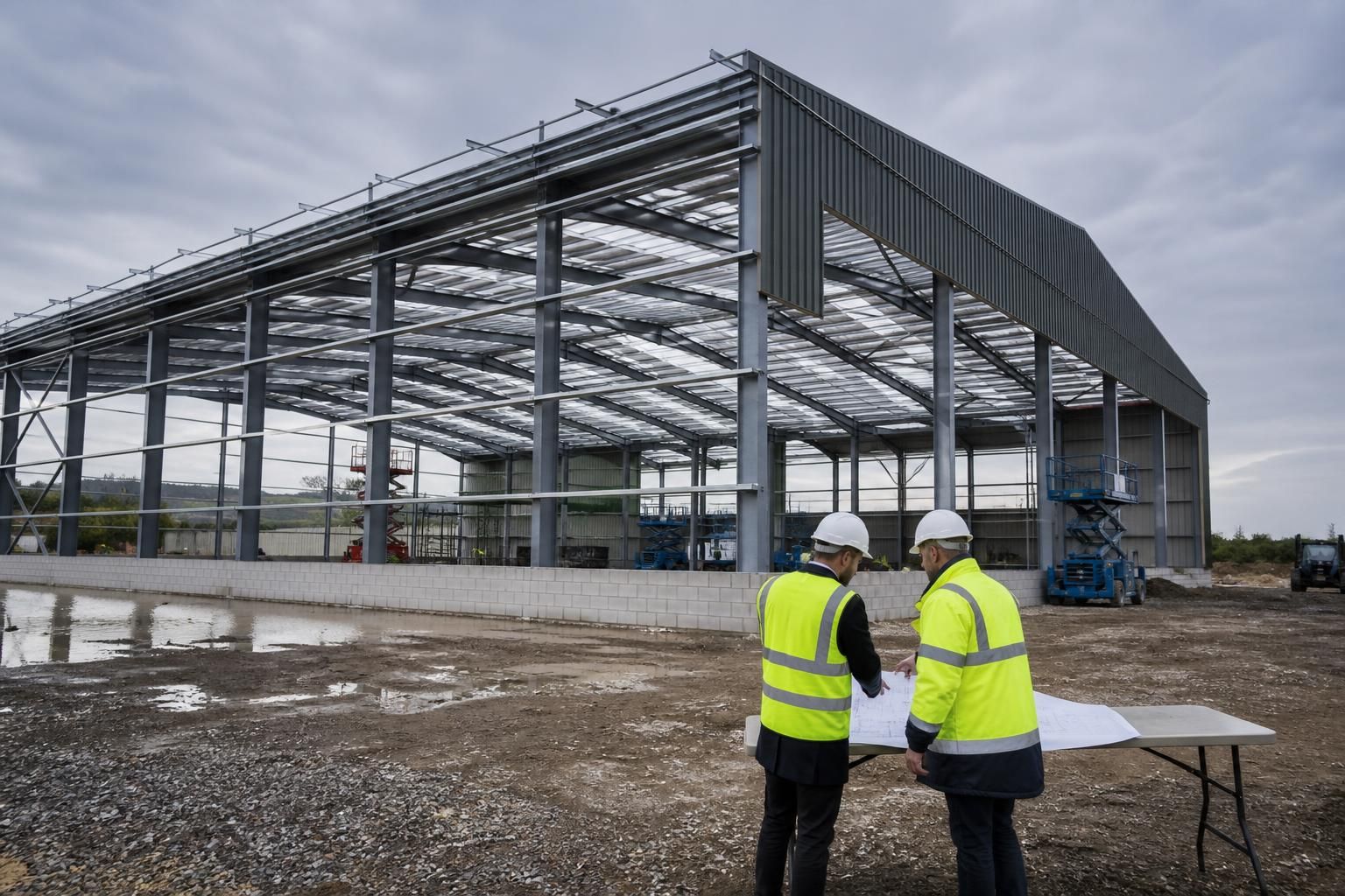
How large should your commercial steel frame building be?
A commercial steel frame building should be large enough for its required activities, equipment, storage, circulation and services, while fitting within the site and planning constraints. Allowing for likely future expansion at the design stage can prevent the building becoming restrictive as the operation develops.
The correct size for a commercial steel frame building is determined by the operational layout, not simply by the available site area. Establish the required clear floor area, internal height, access arrangements, storage capacity and service zones first, then test the proposed footprint against planning, drainage, yard and boundary constraints.
Begin with a written schedule of the activities the building must support. This should identify machinery, workstations, stock, vehicles, loading areas, offices, welfare facilities and any space needed for maintenance or inspection. Record the dimensions and operating clearances of large items rather than allowing only for their footprint. A machine may need room for doors to open, materials to be positioned or components to be removed safely.
Separate the building into functional zones before choosing its overall dimensions. A typical arrangement may include:
- production, fabrication or processing space;
- raw-material and finished-goods storage;
- vehicle movement and loading areas;
- plant rooms, utilities and service routes;
- offices, welfare facilities and staff access; and
- fire-protected routes, exits and areas required for safe circulation.
This approach helps prevent a common sizing error: adding together the footprints of individual items without considering how people, forklifts, vehicles and materials move between them. A compact plan may have a smaller construction footprint but perform poorly if it creates awkward circulation or repeated handling. Conversely, unused space can increase construction, fit-out and heating requirements without improving the operation.
Choose the span and grid around the internal use. Steel framing can provide large, unobstructed areas, which may be valuable for machinery, storage or vehicle access. The most suitable span is the one that supports the required arrangement while remaining compatible with the structural design, roof loading, crane requirements and installation of services. Internal columns may be acceptable in some storage or agricultural layouts but restrictive in manufacturing or vehicle-handling areas, so the column positions should be agreed before the frame is developed.
Internal height also affects the building’s useful capacity. Allow for the tallest equipment, stacked goods, lifting operations, ventilation equipment, lighting, sprinklers and other services. Where overhead cranes, doors or conveyors are proposed, their operating envelope must be considered alongside the roof structure. Increasing height does not automatically provide usable storage; the floor, racking, lifting equipment and fire strategy must all support that arrangement.
Access openings should be sized for the largest vehicle, load or item that will enter the building, with suitable clearance for manoeuvring. Consider the approach from the external yard as well as the opening itself. A door that is wide enough in isolation may still be impractical if turning space, loading positions or segregation between vehicles and pedestrians has not been planned. Personnel doors and emergency exits should be positioned to suit the circulation plan and the building’s fire safety design.
The external footprint must include more than the steel frame. Site planning may need space for access roads, turning areas, parking, loading, hardstanding, drainage, service connections, fuel or waste storage, landscaping and boundary setbacks. Levels, ground conditions and surface-water arrangements can influence where the building can sit and whether the proposed footprint is practical. Planning elevation drawings can help test the building’s proportions and relationship with the site before detailed fabrication information is produced.
Size the building for the operation’s credible development rather than for every conceivable use. Future provision may take several forms:
- a larger initial footprint with part of the space left adaptable;
- an arrangement that allows an extension to be added at a gable or side elevation;
- foundations, frame connections or services planned to support a later phase; or
- a flexible internal grid that can accommodate different machinery, storage or work areas.
Any future-extension strategy should be considered with the initial structural design, fire separation, drainage, access and planning position. An extension that appears straightforward on paper may be limited by neighbouring land, yard circulation, services or the capacity of the original frame and foundations. It is therefore better to record the intended growth route during the design stage than to assume that additional space can be added later without modification.
A practical sizing exercise should produce a scaled layout showing equipment, storage, vehicle routes, pedestrian routes, doors, offices, welfare areas and service locations. Review this drawing with the people who will use and manage the building. Check whether stock can be received, stored, moved and dispatched without crossing incompatible routes, and whether maintenance access remains available when the building is fully occupied.
Buildings UK Ltd can develop bespoke design information for a proposed commercial steel frame building, including planning elevation drawings and isometric fabrication blueprints. These drawings allow the footprint, height, frame arrangement and openings to be reviewed as a coordinated design rather than as isolated dimensions. The final size should be confirmed against the operational brief, site constraints, structural requirements and applicable planning and building-control considerations.
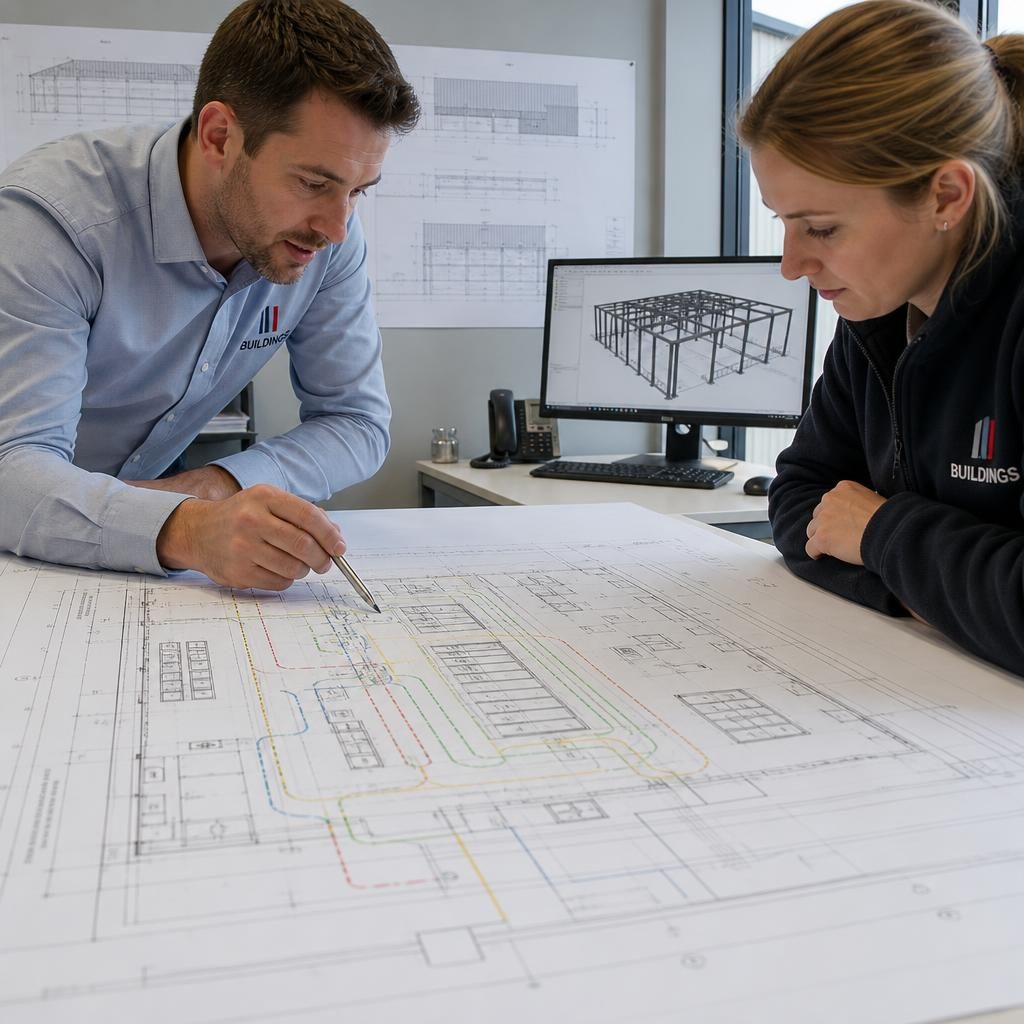
When comparing building dimensions, distinguish between the external footprint, structural grid and usable internal floor area. Wall build-ups, partitions, protected enclosures, service risers and fixed plant all reduce the space available for the main operation. Confirm how dimensions are measured and prepare the layout using the clear internal area, rather than assuming that the outside dimensions represent usable space.
The same distinction applies to height. The underside of the roof structure may be higher than the practical clearance below lighting, ventilation, sprinklers, cranes or other services. Recording both structural dimensions and operational clearances gives a more accurate basis for deciding how large the building needs to be.