
How are steel frame homes insulated?
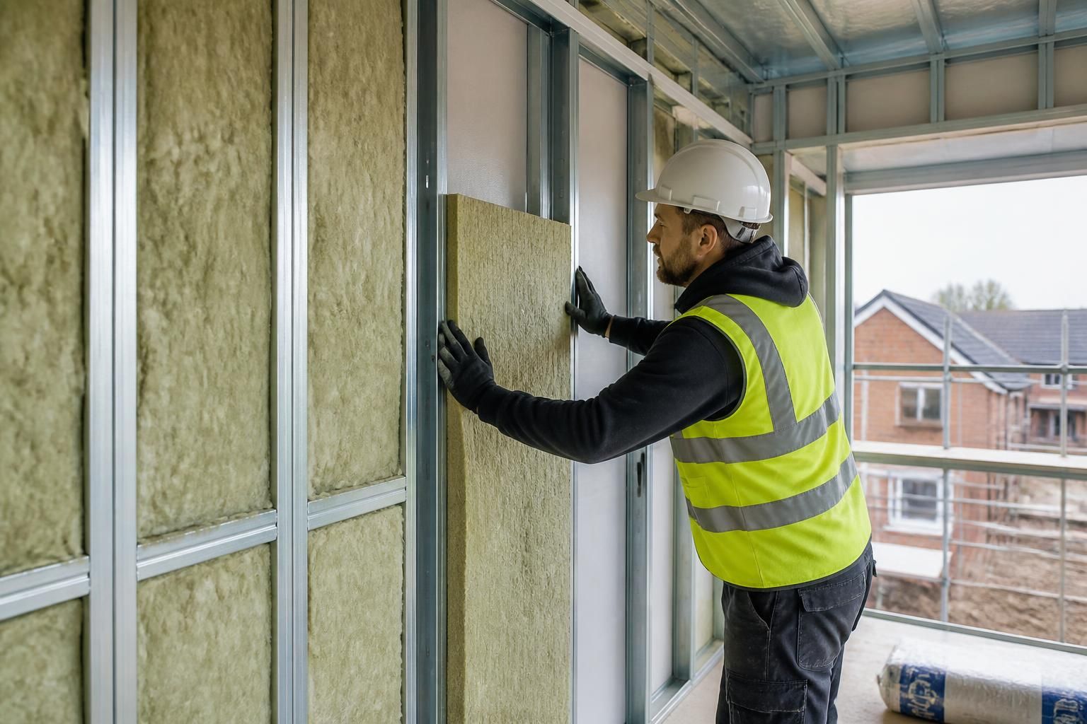
Steel frame homes are insulated using a combination of insulation between or around the steel studs, with a continuous external layer often added to reduce thermal bridging through the frame. The build-up also incorporates suitable airtightness and moisture-control layers, designed as part of the wall, roof and floor specification to achieve effective thermal performance.
Steel frame homes are insulated by creating a continuous thermal envelope around the structural frame, while controlling heat flow at the steel members, junctions and openings. The insulation strategy normally combines a suitable wall build-up with insulated roof and floor elements, thermal-break details, airtight layers and moisture control.
Why steel requires careful detailing
Steel conducts heat more readily than most insulation materials. If insulation is placed only between the studs, the metal sections can provide routes for heat to pass through the wall. These routes are known as thermal bridges. They can reduce the overall performance of the wall and create colder internal surfaces where condensation may occur.
The design therefore considers the wall as a complete system rather than judging the insulation between each individual stud. A layer that runs continuously across the frame can reduce the effect of the steel members. Thermal breaks may also be incorporated where steel connects to other components, including brackets, rails, lintels, window surrounds and roof or floor junctions.
Typical wall insulation arrangements
- Insulation between the studs: insulation is fitted within the spaces formed by the steel framing. This makes efficient use of the available depth, although the frame itself still needs to be addressed in the overall thermal calculation.
- Insulation on the outside of the frame: an external layer helps maintain continuity across the structural members and reduces direct heat paths. It is commonly combined with a suitable sheathing and external cladding or masonry finish.
- Insulation on the inside: an internal layer can supplement the main insulation and help improve the continuity of the thermal envelope, provided it is coordinated with the vapour-control and services strategy.
These approaches may be used individually or together, depending on the frame design, available wall thickness, external finish, internal finish and required thermal performance. The layers must be specified as a compatible build-up; adding insulation without checking the position of membranes, fixings and ventilation paths can create moisture problems.
Roof and floor insulation
Heat is also lost through the roof and floor, so insulating the walls alone is not sufficient. Roof insulation may be positioned between, below or above structural members, with the chosen arrangement designed to limit gaps at rafters, purlins, eaves and roof penetrations. At the floor, insulation can be placed within the floor construction or below a slab, depending on the foundation and floor system. The perimeter needs particular attention because it connects the floor, wall and foundation and can otherwise form a significant thermal bridge.
Airtightness and moisture control
Insulation works most effectively when uncontrolled air movement is prevented. An airtight layer is formed using an appropriate membrane, board or sealed internal lining, with joints and penetrations carefully taped or sealed. Electrical cables, plumbing, ventilation ducts and structural fixings must be planned so they do not unnecessarily puncture this layer.
Moisture-control layers are positioned according to the construction method and the movement of water vapour through the wall. The specification should assess the risk of interstitial condensation, particularly around steel members and at junctions. Vapour control, weather resistance and any required ventilation or drainage cavity must work together rather than being treated as separate additions.
Windows, doors and junctions
Openings often determine whether the insulation strategy performs as intended. Window and door frames should align with the insulation zone where practical, with the surrounding cavity, seals, lintels and reveals detailed to maintain continuity. Similar care is needed at corners, wall-to-roof connections, wall-to-floor connections and changes in construction. Small uninsulated gaps at these points can have a disproportionate effect on surface temperatures and comfort.
How performance is checked
The proposed build-up is assessed using the thermal properties of its materials, the geometry of the steel frame and the details at repeating and non-repeating thermal bridges. This helps establish whether the wall, roof and floor meet the required performance for the project. Drawings should show the position of each insulation layer, membrane, fixing and junction detail rather than relying on a general note that the building will be insulated.
Site installation is equally important. Insulation should be fitted without compression, voids or unnecessary gaps, and boards or rolls should meet tightly around services and framing. Seals and membranes need to remain continuous, while damaged materials should be repaired before finishes conceal the work. A well-designed steel frame home can therefore achieve effective energy performance, but the result depends on the complete specification and the accuracy of its construction, not simply on the nominal thickness of insulation.
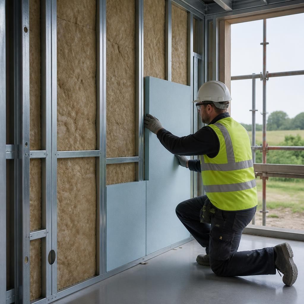
Insulation for a steel frame home is selected for more than its thickness or thermal rating. The material must suit the wall, roof or floor build-up and work alongside the sheathing, membranes, fixings and finishes. Mineral wool, rigid insulation boards and other systems may be appropriate, but their suitability depends on the detailed construction rather than the material name alone.
Selection may also take account of acoustic performance, reaction to fire, moisture tolerance, dimensional stability and the space available within the frame. Boards need accurate cutting and close-fitting joints, while flexible insulation must remain properly supported and avoid becoming compressed. The specification should therefore assess the complete assembly, including how it will be installed and maintained at edges, penetrations and service zones.