
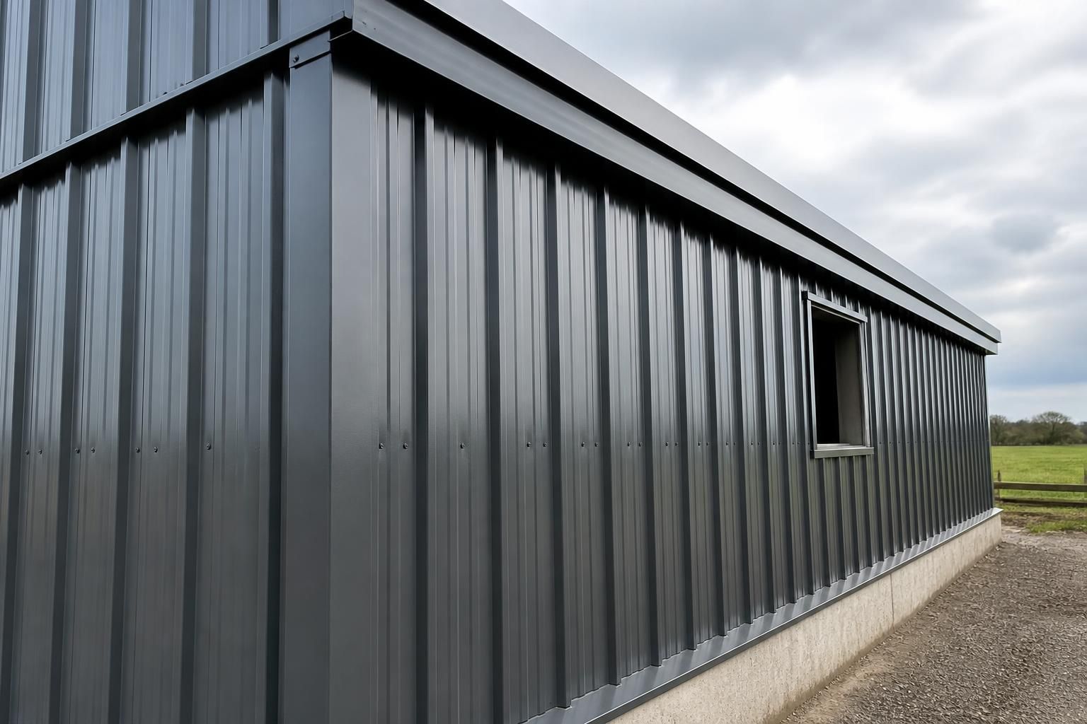
What trims are needed for corrugated metal wall cladding?
Corrugated metal wall cladding typically needs base trims, external and internal corner trims, and trims at eaves and verges. Additional flashings may be required around doors, windows and wall junctions to conceal cut edges and maintain a neat, weather-resistant finish.
Trims for corrugated metal wall cladding are formed flashings that cover exposed sheet edges and changes in direction, helping to direct rainwater away from the building envelope. The correct set depends on the cladding profile, roof and wall arrangement, openings, internal layout and the way the sheets meet adjoining materials.
What each trim must achieve
A trim should provide a continuous, durable transition rather than simply conceal a cut edge. It needs to suit the corrugation so that it sits closely against the sheet, while allowing for the sheet thickness, movement and the fixing method. Poorly matched sections can leave gaps at the profile, create points where water can track behind the cladding or make the finished elevation look uneven.
At the lower edge of a wall, the detail should control water falling from the sheet and keep the bottom edge clear of standing moisture. At changes in direction, the trim should bridge the junction without flattening or distorting the corrugations. Where cladding meets a roof, parapet, masonry wall or another material, the flashing must be shaped to accommodate both surfaces and maintain a continuous drainage path.
Profile and material compatibility
Trim profiles should be selected to match the corrugated sheet rather than chosen as a generic angle or folded strip. Important checks include:
- the corrugation pitch and depth;
- the sheet gauge and resulting edge thickness;
- the angle of the junction;
- the intended direction of water flow; and
- compatibility between the trim coating and the cladding finish.
Using compatible coated steel helps reduce differences in appearance and limits the risk of premature corrosion caused by unsuitable materials. Dissimilar metals should not be brought into direct contact where this could produce galvanic corrosion. Cut edges, drilled holes and damaged coatings should be treated in accordance with the cladding and trim manufacturer’s instructions.
Openings and penetrations
Door and window openings require carefully formed edge details. The trim should cover the cut sheet edge, return into the opening where required and connect with the surrounding weathering layers. At the head of an opening, the detail should shed water to each side rather than allowing it to run into the frame. Side details need to remain sealed without preventing drainage, while the lower junction should avoid creating a trough where water or debris can collect.
The same principle applies to service penetrations, vents and other interruptions in the cladding. The opening should be accurately marked and cut, with the surrounding flashing arranged so that water passes over the detail rather than behind it. Sealant can support the weathering detail, but it should not be treated as a substitute for correctly shaped and lapped metalwork.
Laps, seals and fixings
Where one length of trim joins another, the overlap should follow the system’s installation guidance and face away from the dominant direction of water flow where practicable. Joints should be supported, aligned and sealed with a product suitable for external metal cladding. Excess sealant should not obstruct drainage channels or be used to disguise an incorrectly cut section.
Fixings should be compatible with the trim and supporting structure, positioned to hold the flashing securely without over-tightening and deforming the metal. Fastener heads and washers need to provide a weather-resistant closure, particularly where they pass through exposed sections. The fixing pattern should follow the specified cladding system rather than being decided solely by appearance.
Inside and outside details
External junctions are usually designed to shed water over the face of the cladding. Internal junctions need a different arrangement because their main function is to close the gap, protect the substrate and provide a clean internal finish. In buildings with lined walls or insulation, the trim detail may also need to coordinate with the vapour control layer, insulation thickness and internal lining.
At wall-to-roof interfaces, trims must work with the roof sheets, roof insulation and eaves construction. The final arrangement may include closures or fillers shaped to the profile, but these should be specified as part of the complete building envelope detail. Leaving a gap beneath a flashing can permit wind-driven rain, insects or birds to enter, while sealing every gap indiscriminately can interfere with intended ventilation.
How to specify the trims
Before ordering, prepare the cladding profile, sheet thickness, coating finish, building elevations and a schedule of all junctions and openings. Measurements should include the overall lengths, corner directions, returns, overlaps and any allowances required by the manufacturer’s system. Fabrication drawings are particularly useful where several materials meet or where the building has non-standard angles.
Trims should be installed in a planned sequence so that upper flashings discharge onto, rather than behind, lower weathering elements. Check that each length is straight, the corrugations remain undamaged and all laps are supported and sealed as specified. A final inspection should look for exposed cut edges, open joints, trapped water, distorted fixings and sealant that has split or detached.
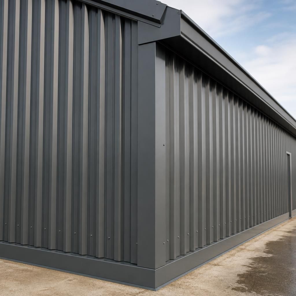
Trim names can vary between cladding systems, so an “eaves trim” may refer to the visible flashing, a profile closure, or a separate gutter-related component. These parts perform different functions and should not be treated as interchangeable. A closure follows the corrugation to close the profile, while the flashing forms the weathering edge; the gutter arrangement may require its own support or apron detail.
When reviewing a quotation or fabrication drawing, check that each trim is identified by its position and purpose, such as wall base, external corner, internal corner, eaves, verge, opening or junction. This avoids receiving a collection of generic folded angles that may not suit the profile or connect correctly with the rest of the building envelope.