
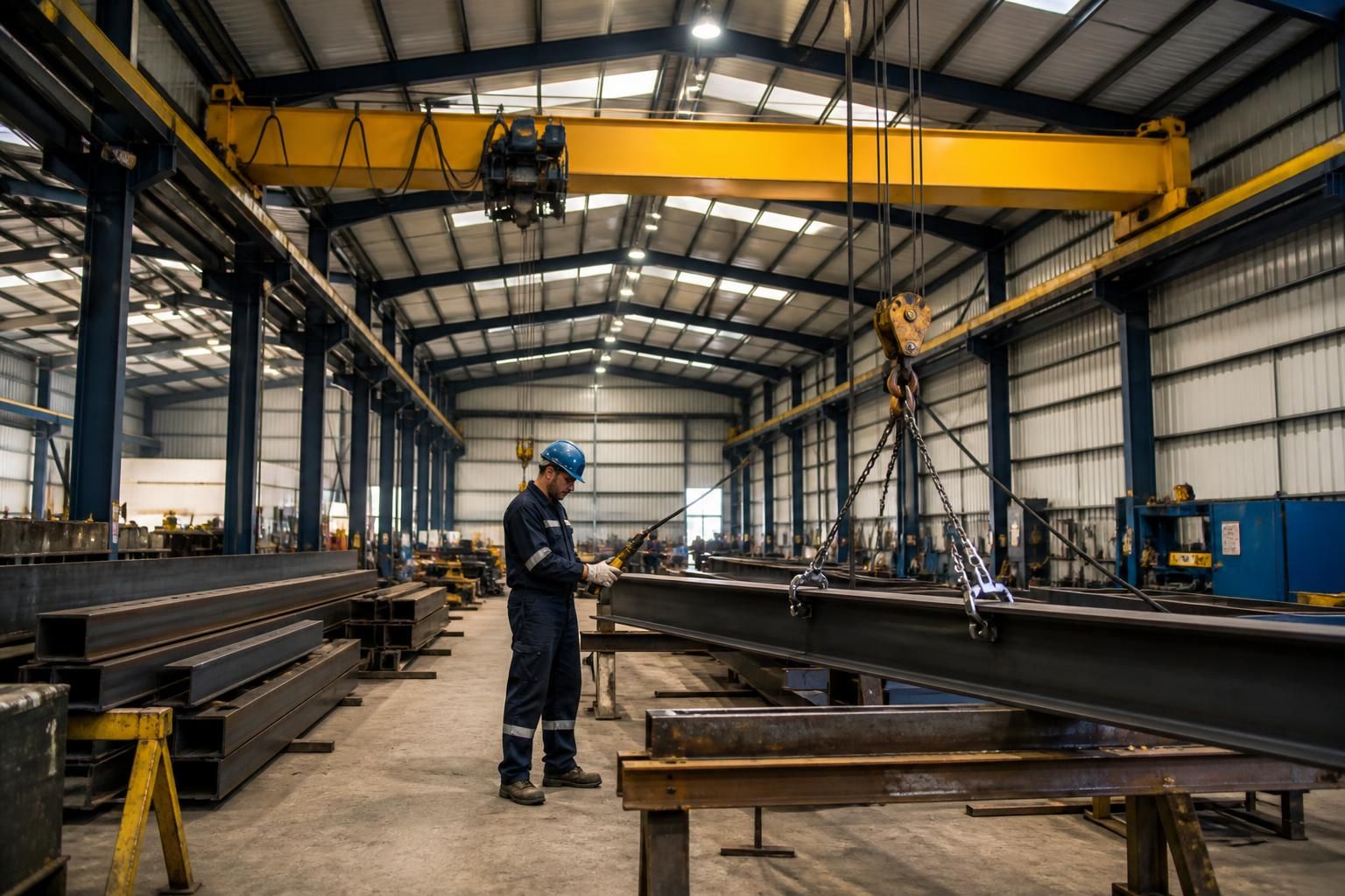
Can steel workshop buildings accommodate overhead cranes?
Yes. Steel workshop buildings can accommodate overhead cranes when the frame, crane runway beams, connections and foundations are designed for the crane’s required lifting capacity, span and operational loads from the outset.
An overhead crane is integrated into a workshop as part of the building’s structural and operational design, rather than treated as an item that can simply be attached to a standard steel frame later. The crane arrangement must suit the loads being lifted, the way the equipment will be used and the available internal space.
Several crane configurations may be suitable for a steel workshop, depending on the work carried out inside it:
- Top-running cranes: the crane travels along rails supported by runway beams, usually positioned on brackets or columns within the main frame.
- Under-running cranes: the bridge runs beneath the runway beams. This can make better use of the roof space in some buildings, although the supporting arrangement still needs careful design.
- Gantry cranes: the crane is supported by legs that travel on floor-level rails. These may be appropriate where the building frame is not intended to carry the runway loads, but they require clear floor routes and suitable foundations.
- Jib cranes: a smaller slewing arm serves a defined workstation or bay. It may be fixed to a column, wall or independent foundation, subject to the capacity of that support.
For a travelling overhead crane, the structural design normally includes dedicated runway beams, rail supports, brackets, crane columns or strengthened portal-frame members. These components have to resist more than the crane’s parked weight. The design must account for the lifted load, the hoist and bridge weight, trolley movement, braking forces, acceleration, sway and the repeated nature of crane operations. Horizontal forces can be particularly important because they are transferred through the runway system into the building frame and foundations.
The crane’s working capacity is only one part of the specification. A designer will also need information about the crane span, the distance it must travel, hook height, lifting frequency, duty classification, wheel loads and the position of the rails. The required clearances should be established at the same time. These may include space above the highest load, clearance from roof members, room for maintenance access and safe separation from doors, lights, services and other equipment.
Foundations are an equally important consideration. Crane reactions can be concentrated at particular columns or support points, while repeated movement may impose additional demands on the ground-bearing system. The foundation arrangement may therefore differ from that used for a workshop without lifting equipment. Ground conditions, column positions and any independent crane supports should be reviewed by the structural designer rather than assumed to be suitable.
A workshop can also be designed with future crane installation in mind, even if the lifting equipment is not being fitted immediately. This requires a clear understanding of the likely future crane duty and layout. Allowing only for a general “possible crane” without defining the anticipated loads may leave the frame, foundations or clearances inadequate. If the future requirement is uncertain, the design should identify the assumptions and limitations clearly.
Internal planning affects the usefulness of the crane. The building width and length should provide sufficient travel along the intended route, while columns, bracing and mezzanine structures should not obstruct the lifting zone. Vehicle access, fabrication benches, storage areas and pedestrian routes should be arranged so that the crane can move loads without creating unnecessary conflicts. Crane coverage should be mapped across the floor rather than judged solely by the building’s external dimensions.
Where a crane is supported by the building, the connection details need particular attention. Bolted or welded connections must transfer vertical and horizontal actions safely, and local strengthening may be required around brackets, rails or column flanges. Fabrication drawings should show the position and specification of these interfaces so that the steelwork, crane equipment and installation work are coordinated correctly.
There are also safety and compliance duties beyond the building frame itself. The completed lifting equipment must be selected, installed, examined and operated in accordance with the relevant UK requirements. The responsible parties should establish requirements for safe working loads, emergency stopping, control systems, inspection access and ongoing thorough examination. A crane supplier, structural engineer and building designer should exchange information before manufacture and installation, particularly where the crane is connected directly to the workshop structure.
For a quotation or technical design, useful information includes the proposed crane type, safe working load, span, runway length, hook travel, lifting frequency, duty classification, preferred support arrangement and the loads or specifications provided by the crane manufacturer. A building plan showing doors, machinery, storage zones and required clear heights will help identify clashes at an early stage.
In practice, the most reliable approach is to design the workshop and crane support system as one coordinated package. This allows the frame, runway beams, connections, foundations, access arrangements and internal clearances to be checked together, reducing the risk of costly strengthening or alterations after the steelwork has been manufactured.
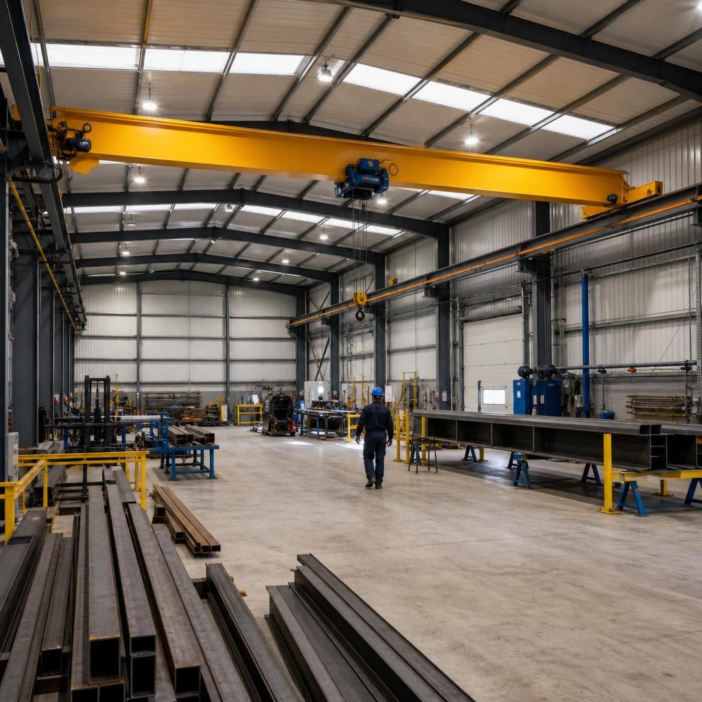
Runway alignment is a separate consideration from the strength of the workshop frame. Rails must be installed at the correct level, spacing and alignment so the crane wheels travel evenly along the full route. Fabrication tolerances, column movement and installation accuracy can all affect this, particularly over longer runway lengths.
The steelwork drawings should therefore define the runway geometry and connection details clearly, while the crane installer verifies the completed supports before commissioning. Correct alignment helps limit uneven wheel loading, unwanted movement and premature wear, and provides a reliable basis for future inspection and maintenance.