
How are steel roof panels detailed around roof penetrations?
Steel roof panels are detailed around penetrations by coordinating their positions with the structural layout, then forming neat openings with suitable trims, curb details, flashings, closures and compatible seals. The design must allow for water shedding, thermal movement and secure fixing without distorting the panels or compromising the roof’s weather resistance.
Roof penetration detailing is the method used to take a pipe, duct, rooflight, flue, fan, outlet or other service through a steel roof panel while preserving the roof’s structural continuity and resistance to rain. The detail is developed for the specific penetration, panel profile, roof build-up and supporting steelwork rather than treating every opening in the same way.
Begin with a coordinated penetration schedule. Each opening should be identified before the panels are fabricated or installed. The schedule normally records the penetration’s purpose, dimensions, finished level, position in relation to the steel frame, required upstand or curb, insulation requirements and any access or maintenance zone. Large or concentrated openings should be reviewed against the purlin arrangement, as cutting a panel does not remove the need to maintain adequate support around its perimeter.
- Keep penetrations clear of panel end laps, side laps, ridge details and valley gutters wherever the design permits.
- Allow enough space for trims, fasteners, sealant application and future inspection.
- Check that discharge from the penetration or its flashing cannot run against a lap or into an unprotected panel joint.
- Coordinate the position with internal equipment, suspended services and the intended drainage falls.
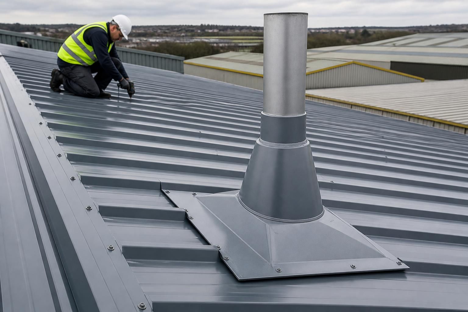
Small penetrations, such as pipes and cables, are generally formed with a purpose-made sleeve, pipe flashing or weathering collar. The collar must suit the roof profile and be compatible with the panel coating and sealants. It is fixed to the panel without crushing the profile, and the upper edge is arranged so water flows over the flashing rather than behind it. Profile fillers or closures may be required where the flashing crosses corrugations or ribs, preventing wind-driven rain and insects from entering the roof build-up.
Larger penetrations, including ducts, rooflights, smoke vents and plant openings, usually need a raised curb or kerb. The curb provides a continuous, stable edge to which the weathering detail can be secured. Its height and construction depend on the roof system, insulation thickness, maintenance requirements and the equipment being installed. Flashings should turn up against the curb and include properly formed corners; flat folded joints alone are not a substitute for a continuous weathering arrangement.
Where an opening interrupts the panel’s normal bearing or crosses a purlin line, additional framing may be required around it. Trimmer members transfer loads back into the surrounding structure and limit movement at the opening edge. Their size, connection and location should be established by the project’s structural design. Panels should not be expected to carry equipment, access loads or unsupported curb loads unless that capacity has been specifically verified.
The cutting method matters. Openings should be set out from the approved drawings and cut with equipment that leaves a clean edge without excessive heat damage or distortion. Abrasive cutting can damage protective coatings and leave hot particles embedded in the finish, so the selected method should be suitable for the panel material and coating. Cut edges should be treated in accordance with the panel and coating requirements, with swarf removed from the roof so it does not cause staining or corrosion.
Flashing and trim joints need a planned sequence. Lower or downslope pieces are normally installed so that upper pieces overlap them in the direction of water flow. Corners should be folded or formed to avoid open pathways, and end laps should have the specified sealant or sealing strip placed continuously and neatly. Sealants must remain compatible with the panel finish, flashing material, insulation and any membrane used beneath the outer sheet. Random patches of sealant are unreliable because they can leave unsealed channels and make later inspection difficult.
Weather seals are only one part of the detail. The penetration must also maintain the continuity of the insulation and the internal vapour control layer where these form part of the roof construction. Gaps around a curb or sleeve can create cold bridges, air leakage and local condensation. Insulation should be cut and fitted closely around the opening, while the internal lining or vapour layer should be sealed to the penetration with a suitable proprietary or project-approved method.
Thermal and structural movement must be allowed for at the interface. Steel panels, flashings, curbs and service components can expand, contract or deflect at different rates. Details therefore need appropriate laps, slotted connections or flexible seals where movement is expected, while still preventing the fasteners from loosening or the flashing from tearing. Rigidly bridging components that move independently can produce splits, distortion or leakage around the penetration.
Fire and smoke requirements should be checked where a penetration passes through a fire-resisting roof or separates areas with different fire performance requirements. A standard weathering collar may not provide the necessary fire stopping. The penetration detail may need tested fire-resistant components, protected supports or a specified seal around the service, selected by the designer to match the roof construction and service type.
Installation should follow the approved setting-out information rather than relying on measurements taken from a panel after it has been fixed. A practical sequence is:
- Confirm the penetration location, dimensions, levels and supporting steelwork.
- Install any required trimmers, curb framing or support brackets.
- Fit the surrounding roof panels and verify the opening before fixing the final trim.
- Form the opening and protect the exposed panel edge as specified.
- Install closures, insulation interfaces, sleeves, curbs and flashings in the designed overlap sequence.
- Apply compatible seals and install fixings to the specified pattern and tightness.
- Inspect laps, corners, fastener washers, drainage paths and internal interfaces before the area is covered or handed over.
Inspection should look for crushed ribs, over-tightened fasteners, missing closures, incomplete sealant runs, exposed cut edges, ponding points and flashings that terminate short of the surrounding roof. The finished penetration should also be checked after associated equipment has been installed, since brackets, cable trays and access arrangements can interfere with the original weathering detail.
For bespoke steel-framed buildings, penetration information is best incorporated into the design and fabrication drawings before manufacture. Buildings UK Ltd can include planning elevation drawings and isometric fabrication blueprints within its design packages, providing a basis for coordinating roof openings with the structural frame and panel arrangement. The final detail should remain subject to the project’s structural, fire, insulation and roofing specifications.
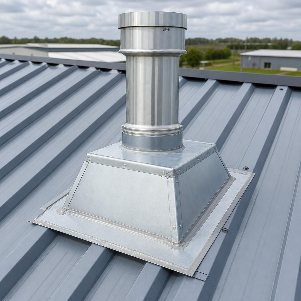
Penetration dimensions should distinguish between the service size, the sleeve or kerb’s external dimensions, and the finished roof opening. Allowance may also be needed for insulation, fire-stopping components, movement and the clearance required to install the flashing. Cutting an opening to the pipe or duct size alone can leave insufficient space for a secure, watertight detail.
The approved drawings should identify the finished opening and its relationship to the roof panel profile. This gives the installer a reliable reference for positioning the kerb or collar and avoids adapting the weathering detail around an opening that has been cut too small, too large or in the wrong location.
Discuss Your Roof Penetration Design
Discuss your proposed roof penetrations with Buildings UK Ltd to review the opening requirements alongside the building’s structural and panel design. Provide the available service, equipment and roof layout information so the appropriate detailing approach can be considered.