
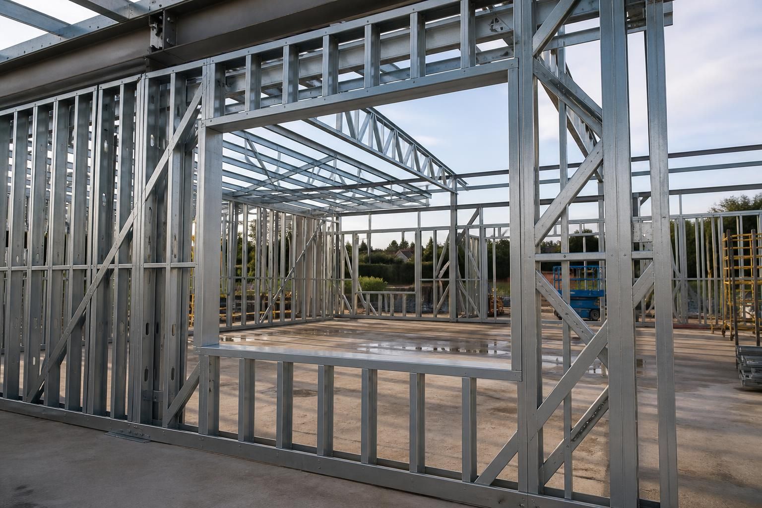
What are the structural limits of light gauge steel framing?
The structural limits of light gauge steel framing are governed by the section thickness and geometry, steel grade, span, applied loads, restraint and connection design. Its capacity is therefore project-specific: members may be limited by bending, shear, deflection or local and overall buckling, so structural calculations are needed to confirm whether a proposed frame is suitable.
Light gauge steel framing is most limited when thin-walled members must carry compression or bending over relatively long, insufficiently restrained lengths. The practical boundary is reached when buckling, deflection, connection behaviour, fire performance, robustness or construction tolerances cannot be adequately controlled. There is no single maximum load or span for all light gauge systems; the permissible size depends on the complete structural arrangement and its intended use.
Section slenderness is a primary limitation. Light gauge members usually have a high width-to-thickness ratio. Parts of the section can therefore buckle locally before the full yield strength of the steel is reached. Design calculations may use effective section properties, reducing the area or resistance assigned to slender webs, flanges and lips. A section that appears adequate based only on its gross dimensions may have a substantially lower usable capacity once local buckling is considered.
Several forms of instability may need to be checked separately:
- Local buckling: an individual plate element, such as a flange or web, buckles between its supporting edges.
- Distortional buckling: part of the cross-section deforms, often involving a flange and its edge stiffener.
- Flexural or flexural-torsional buckling: the whole member moves sideways, twists or does both when its unrestrained length is significant.
- Web crippling: a concentrated reaction or applied load causes local failure in the web near a support or point load.
These behaviours mean that adding steel thickness, changing the profile geometry or reducing the unrestrained length can be more effective than simply increasing the overall depth of a member. The design must also account for whether sheathing, decking, noggings, bracing or other components genuinely provide restraint. Restraint should not be assumed merely because another material is present; its stiffness, fixings and continuity must be suitable for the load case.
Long spans are generally governed by serviceability as well as strength. A member can theoretically resist the applied load yet deflect too far for the roof, floor, cladding, glazing, partitions or drainage details connected to it. Excessive movement can cause ponding, cracking, misalignment, loss of weather-tightness or damage to finishes. Floor applications may also require checks for vibration and dynamic response, not just static bending resistance. For this reason, acceptable deflection limits and movement compatibility should be agreed at the design stage rather than treated as an afterthought.
Compression members require a reliable load path and lateral stability. Studs, posts and columns may have adequate axial resistance when considered individually but become vulnerable if they are not properly tied into floors, roofs, wall panels or bracing systems. Eccentric loading, imperfect alignment and openings can introduce bending alongside compression. The design should establish how vertical and horizontal actions travel through the frame to the foundations, including the effects of wind, notional imperfections and temporary construction conditions.
Openings and interruptions can reduce capacity locally. Doors, windows, service penetrations and large wall openings remove sheathing or interrupt the continuity of studs and tracks. The surrounding members may then need headers, jamb studs, trimmers, additional bracing or a different load-bearing arrangement. Point loads from beams, plant, roof members or storage systems also need specific bearing details. A standard wall arrangement cannot automatically be assumed to support a concentrated load without checking web resistance, bearing length, fasteners and load distribution.
Connections can control the frame before the steel section does. Screws, bolts, welds and other fixings must transfer axial force, shear, bending and sometimes tension caused by uplift. Thin material can be vulnerable to pull-out, tear-out, bearing failure, net-section failure and local distortion around a fixing. Connection eccentricity can create secondary moments, while insufficiently stiff joints may prevent the frame from behaving as assumed in the calculations. The connection design must therefore match the structural model and the specified installation method.
Light gauge framing is also sensitive to the way it is assembled. Missing fixings, inadequate bracing, incorrect lap lengths, damaged galvanised coatings, unlevel supports or deviations in alignment can reduce the intended resistance. Temporary stability is particularly important: a partially completed wall or roof may not yet have the diaphragm action or restraint available in the finished structure. Erection sequencing and temporary works should be considered where members are exposed to loads before all stabilising components are installed.
Fire performance may impose a lower limit than ambient structural capacity. Thin sections have relatively little steel mass to absorb heat, so their resistance can reduce significantly during a fire unless the system has suitable protection or has been designed for the required fire exposure. Protection must be compatible with the framing, fixings, joints, penetrations and surrounding construction. Fire resistance is a performance requirement for the whole assembly, not simply a property of an isolated steel stud.
Durability and environmental exposure also affect the usable design life. Protective coatings should be selected for the conditions in which the frame will operate, including humidity, condensation, agricultural environments, chemical exposure and contact with incompatible materials. Drainage and ventilation details are important where moisture could become trapped. Corrosion that reduces the already slender material can materially alter the calculated resistance.
In practice, light gauge steel is less suitable where the project demands very high concentrated loads, substantial unbraced spans, heavy suspended equipment, significant impact resistance or large open areas with little opportunity for intermediate restraint. It may still form part of a solution, but heavier rolled sections, portal frames, trusses, reinforced concrete or a hybrid arrangement may be needed for the primary load-carrying elements. The transition is often determined by load concentration, span, fire strategy, connection requirements and the need to limit movement, rather than by building size alone.
A proper limit assessment should include the intended use, geometry, support conditions, floor and roof build-ups, imposed and environmental actions, openings, bracing, fire requirements, durability conditions and the proposed connection details. A structural engineer can then check the relevant limit states using the applicable British and European design provisions, including member resistance, stability, serviceability, connections and foundations. Fabrication and erection drawings should reflect those assumptions so that the completed frame retains the restraint and load paths used in the design.
Published span tables for light gauge steel sections should be treated as design guidance, not universal structural limits. Their values usually depend on a defined member spacing, support arrangement, load case, restraint condition and deflection criterion. Changing the roof or floor build-up, lining arrangement or spacing between members can therefore make a tabulated value unsuitable for the actual project.
When comparing a proposed section with a table, check that the assumptions match the intended construction and loading. A result that satisfies strength may still be unsuitable if the specified movement limit, bearing condition or restraint arrangement differs. Where the project falls outside the stated assumptions, section design and system behaviour should be assessed specifically rather than extrapolating the table.
Discuss the structural limits of light gauge steel framing
Share your proposed layout, spans, loads and intended use with Buildings UK Ltd for an initial discussion about whether light gauge steel framing is appropriate. The team can advise on the information needed for a project-specific design assessment and quotation.