
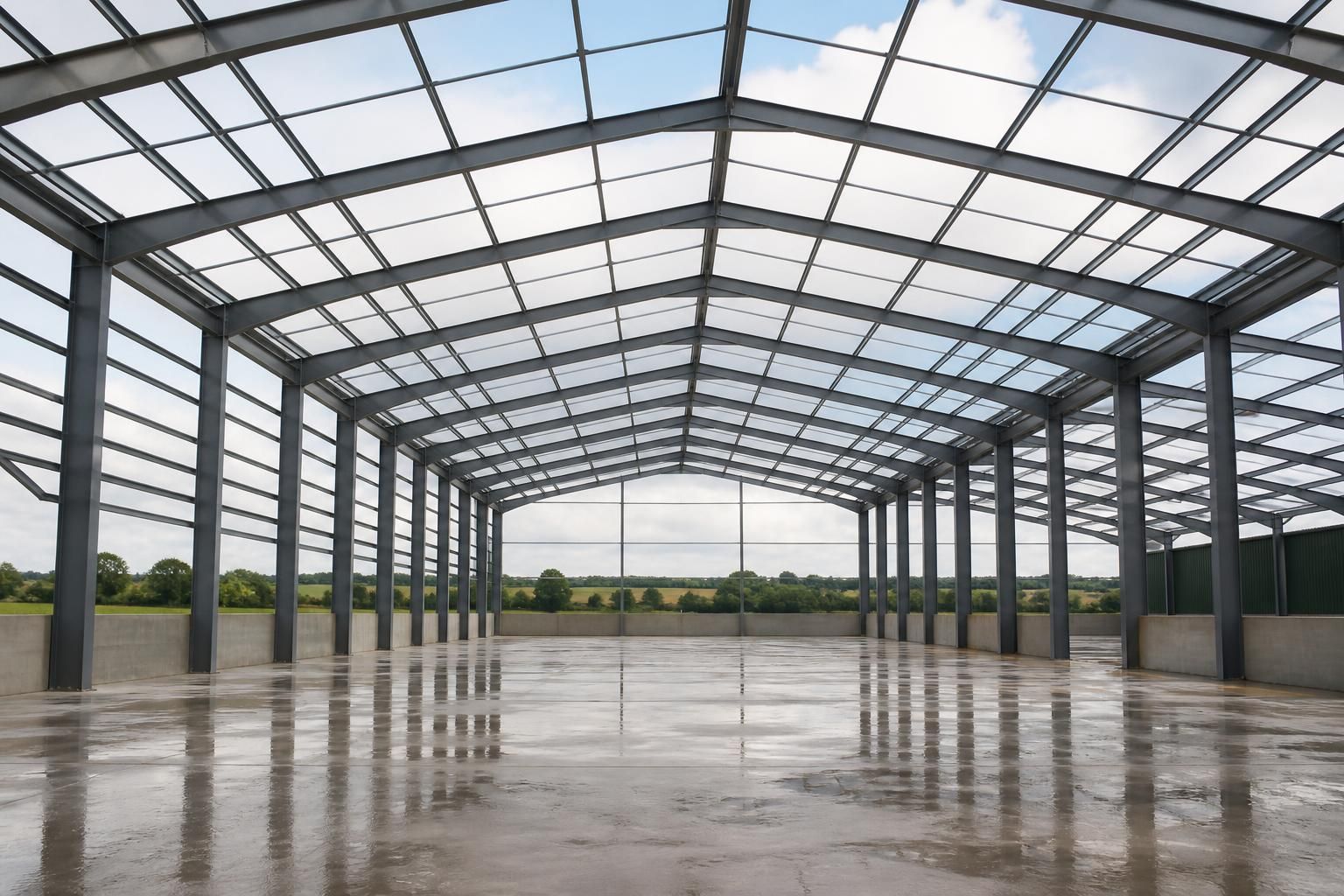
What determines the span of a steel framed building structure?
The span of a steel framed building is determined by the loads it must carry, the building’s use, frame geometry, steel section sizes, connection design and site conditions. Structural calculations balance the required clear internal space with stability, deflection limits, roof and cladding loads, wind exposure and any future requirements.
The span is the clear distance between the structural supports of a steel framed building, and it is set by the required usable width alongside the design checks needed to keep the frame stable and serviceable. A wider clear span generally requires a different frame arrangement, deeper or heavier members, stronger connections, or a combination of these measures.
Clear span and overall building width are not the same measurement. Clear span describes the unobstructed space between the inside faces or structural lines of the supporting columns. Overall width also includes the columns, cladding, eaves details and any external projections. This distinction matters where machinery, vehicle access, storage arrangements or animal accommodation require a completely unobstructed internal area.
The internal layout is often the first practical consideration. A single-span frame can provide a clear floor area across the full width, whereas intermediate columns create multiple narrower spans. Those columns may reduce the steel required in individual rafters, but they can interfere with vehicle movements, crane paths, feed passages, storage bays or production lines. The most suitable arrangement therefore depends on how the floor will be used, not simply on achieving the largest possible opening.
Frame spacing along the length also affects the design. The distance between portal frames determines how loads are transferred into the rafters and columns, while purlins and side rails support the roof and wall cladding between frames. Changing the bay arrangement can alter member sizes, connection forces, foundation reactions and the position of doors or other openings. A span should therefore be considered as part of the complete structural grid rather than as an isolated dimension.
Roof geometry has a direct effect on how a frame carries its forces. Roof pitch, eaves height, ridge arrangement and any changes in level influence the shape and stiffness of the rafters. Large doors, open elevations, rooflights, attached canopies and suspended services may also affect the frame locally. These details need to be allowed for at the design stage, because adding them later can require strengthening or changes to the original support arrangement.
The intended use determines which actions the structure must accommodate. An agricultural building may need space for machinery, stored materials or livestock-related equipment. An industrial building might include handling equipment, suspended services or concentrated loads from fixed plant. An equestrian building may prioritise unobstructed movement, suitable headroom and safe internal clearances. Each use produces different requirements for the frame, cladding supports, foundations and serviceability checks.
Designers also assess how much movement is acceptable, rather than checking strength alone. Excessive deflection can affect cladding joints, doors, roof drainage, suspended equipment or the operation of lifting systems. Vibration and local movement may be relevant where people, animals, vehicles or machinery occupy the building. The permitted movement helps determine whether a proposed long span is practical and whether additional stiffness or support is needed.
Site and construction constraints can limit the span that is sensible. Ground conditions influence the size and form of the foundations, while the position of existing structures, boundaries, access routes and underground services can affect column locations. The building must also fit within its planning envelope and provide the required clearances around doors, yards and neighbouring structures. A structurally possible span may not be the most suitable option once these constraints are considered.
A typical span assessment considers:
- the clear internal width and required headroom;
- the position of columns, doors, partitions and fixed equipment;
- the roof form, frame spacing and cladding support arrangement;
- the imposed, suspended and concentrated loads associated with the building’s use;
- acceptable deflection, vibration and movement;
- wind exposure, ground conditions and foundation reactions; and
- fabrication, connection, delivery and erection requirements.
For this reason, there is no universal maximum span for a steel framed building. The final dimension results from structural calculations and a coordinated design that balances usable space, material efficiency, stability, serviceability and site practicality. Elevation drawings and fabrication information must then reflect the agreed span, frame geometry, openings and connection details so that the manufactured structure matches the building’s intended use.
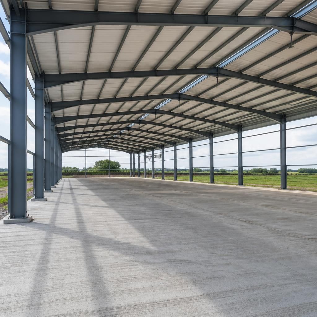
A proposed span is only viable when the complete load path has been checked. Forces travel from the roof through the rafters and connections into the columns, baseplates and foundations, so a rafter may be adequate while the supporting columns, joints or foundations require revision. Foundation reactions and potential settlement can therefore influence the final span as much as the steelwork above ground.
This is why span selection is developed as a coordinated structural solution rather than chosen from a standard table. The frame, connections and foundations must work together under the design actions, with the resulting arrangement recorded in the engineering and fabrication information used to manufacture the building.