
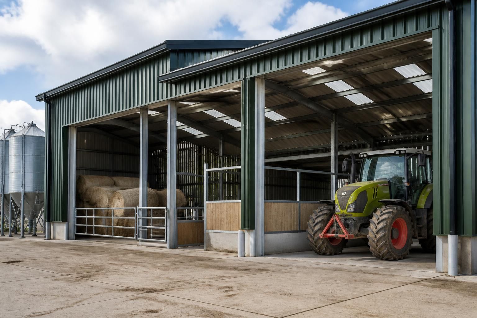
How are agricultural and equestrian building dimensions determined?
Agricultural and equestrian building dimensions are determined by the intended use, required capacity, access for vehicles or machinery, site constraints and planning requirements. The design then sets the appropriate span, length, eaves height, door sizes and structural specifications for activities such as livestock housing, machinery storage, hay storage or horse riding.
Agricultural and equestrian building dimensions are established by converting the building’s practical requirements into a coordinated layout and structural design. The process considers the usable internal area first, then allows for the steel frame, cladding, doors, roof construction, drainage, ventilation and any equipment that must operate safely within or around the building.
Start with the building’s intended use
The same footprint will not suit every agricultural or equestrian application. A machinery shed needs clear access, adequate door openings and enough internal height for the largest vehicles or implements. A livestock building must allow for pen layouts, feeding routes, cleaning and animal movement. Hay, straw and grain storage require efficient use of cubic capacity, while an equestrian building may need space for stables, tack rooms, wash areas, storage or an indoor riding surface.
Before selecting dimensions, the designer should identify:
- what the building will store, house or accommodate;
- the number, size and operating pattern of vehicles, animals or users;
- the equipment that needs to enter, turn or be used inside;
- areas requiring separation, such as stables, offices, workshops or feed stores;
- how materials, feed, bedding, machinery or waste will move through the building; and
- whether the building may need to support a different use later.
This information establishes the required clear width, length, height and circulation space rather than relying on a standard building size.
Plan the internal arrangement before fixing the outer dimensions
A building’s external measurements can be misleading if the internal arrangement has not been considered. The steel frame, wall thickness, cladding build-up and doors all reduce the usable space. For this reason, layouts should distinguish between overall external dimensions and the clear dimensions available for storage, livestock, riding or machinery.
For example, a machinery building may need unobstructed bays so that equipment can be parked and removed without moving other items. A livestock building may need a combination of animal areas, feed passages and handling zones. In an equestrian building, the riding area must be considered alongside kickboards, perimeter clearances, access routes, viewing areas and any supporting rooms. These requirements can influence the frame span, the position of internal columns and the number of bays.
Access determines more than door width
Vehicle and machinery access is assessed by considering the complete approach and manoeuvring route. Door dimensions need to accommodate the largest vehicle or load, with practical clearance for steering, loading and uneven ground. Headroom is equally important where machinery has raised attachments, tipping bodies or loading equipment.
Access planning also considers the position of doors in relation to corners, internal columns, stored materials and opposing entrances. A large door may fit within a wall but still be impractical if the approach is too restricted. Where through-access is useful, door positions can be arranged to support a logical movement pattern and reduce unnecessary handling.
Span, bay spacing and height affect the structure
The required clear span influences the steel frame arrangement and the loads carried by the rafters and columns. A wider unobstructed area may be valuable for machinery or riding, but it also affects structural design, roof construction and foundations. The building length is then divided into suitable bays, taking account of the intended internal layout, door locations and cladding requirements.
Eaves height is selected from the activities taking place inside, not simply from the overall building appearance. It must provide suitable clearance for vehicles, stored materials, ventilation arrangements and equestrian use. The roof profile and pitch also affect the internal volume, rainwater discharge and the amount of cladding required.
Structural calculations take account of factors such as the building geometry, imposed loads, wind exposure, roof and wall materials, openings and site conditions. These checks determine the sizes and connections of the hot rolled steel members, rather than dimensions being chosen solely for convenience or visual proportion.
Site conditions can alter the preferred size
The available site affects the layout through boundaries, ground levels, existing buildings, access roads, drainage routes and services. A building may need to be shortened, repositioned or divided into separate areas to fit the site effectively. Ground investigation and foundation design can also influence the final arrangement, particularly where levels vary or ground conditions require additional consideration.
Planning requirements are relevant to the external envelope and placement. Elevation drawings can show the proposed height, roof form, openings and relationship with the surrounding site. These details help establish whether the selected dimensions are compatible with the planning context before fabrication information is finalised.
Allow for use, maintenance and possible change
Good dimensional planning includes the space needed to inspect, clean, repair and operate the building safely. This can include access around equipment, clearance beneath roof-mounted components, washable or protected areas in livestock facilities and sensible routes for maintenance work.
Where future expansion is being considered, the initial frame layout and site position should be reviewed before construction. Potential extension directions, access to the proposed addition, drainage, door positions and the relationship with existing bays may all affect the most suitable starting dimensions. Planning for this at the design stage can avoid creating a layout that prevents practical extension later.
The final design is normally developed through coordinated drawings: planning elevations communicate the building’s external form, while fabrication or isometric drawings define the steelwork arrangement and connections. Reviewing both the operational layout and the structural information ensures that the proposed width, length, height and openings work together as one design rather than as isolated measurements.
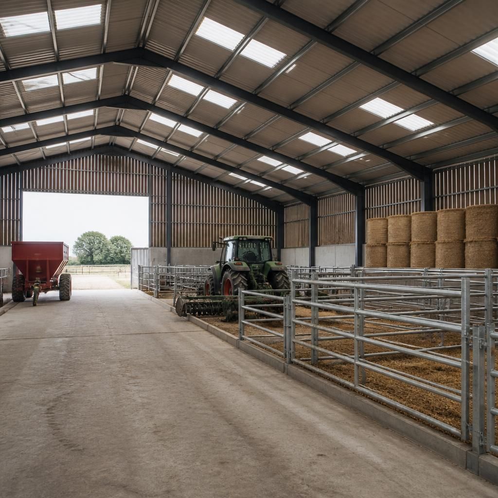
A practical dimensional schedule helps turn the proposed use into measurable requirements before the building envelope is fixed. It should record the dimensions of the largest vehicle, implement, storage unit, stable fitting or riding surface, together with the clearance needed to use it safely. The schedule should distinguish the object’s physical size from its operating envelope, which may include space for doors, attachments, turning, loading or routine inspection.
Each requirement can then be checked against the proposed frame grid and internal finishes. This helps identify conflicts that may not be apparent from the overall width and length, such as a door opening that does not align with the usable bay, a roof truss reducing clearance above equipment, or wall protection affecting stable dimensions. Allowances for construction tolerances and the thickness of cladding, partitions and protective linings should also be included.
- Measure the largest items that will enter or be housed in the building.
- Define the clearance required to operate, clean, load or remove them.
- Check those clearances against the frame, doors, partitions and internal fittings.
- Confirm that the resulting dimensions remain practical for the intended daily use.