
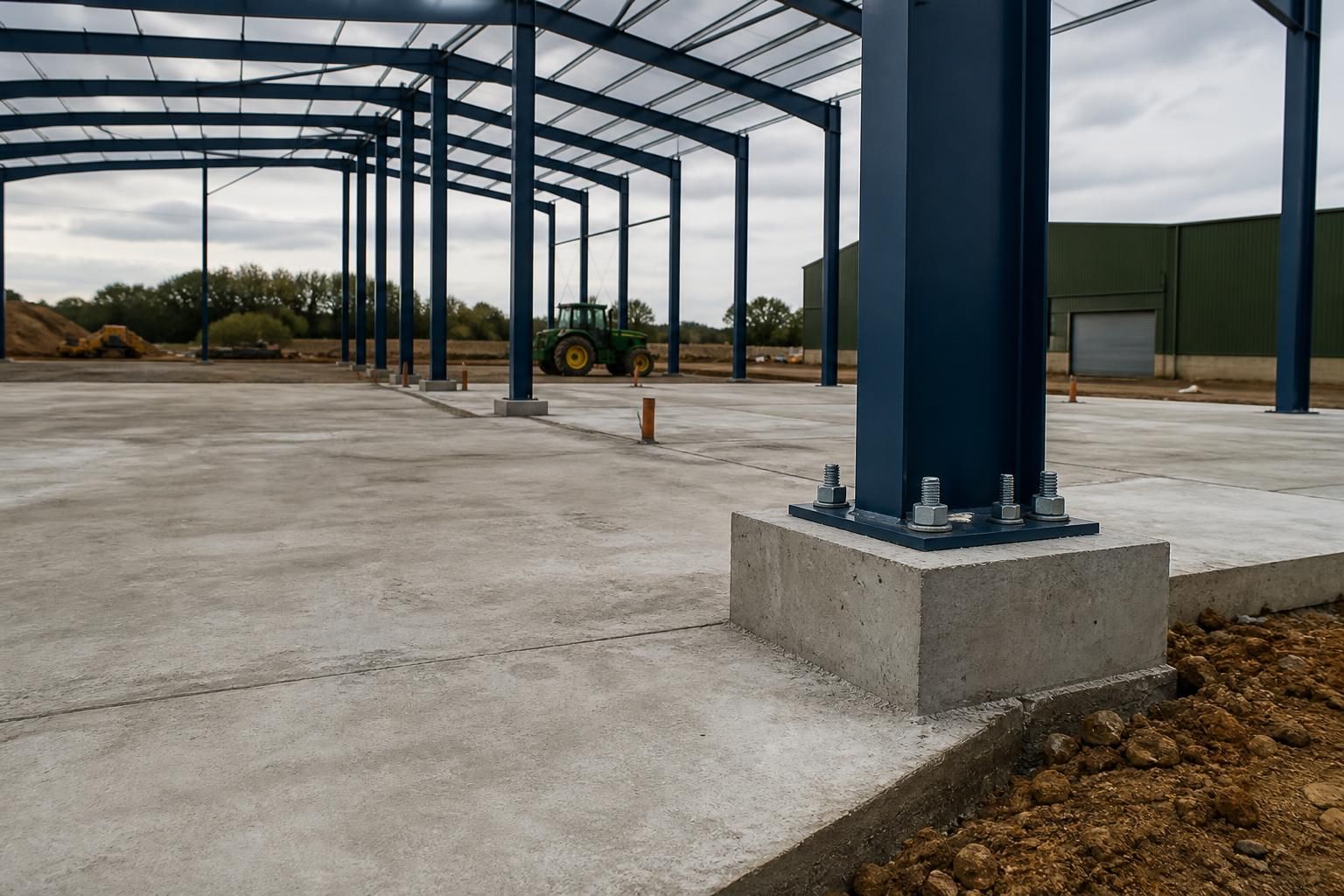
What foundation requirements apply to a machinery shed frame?
A machinery shed frame generally requires an engineered concrete foundation designed around the ground conditions, building loads, frame layout and local site levels. The design should confirm footing dimensions, concrete specification, reinforcement, drainage considerations and the positioning of holding-down anchors so the steel frame can be installed securely.
The foundation for a machinery shed frame must transfer the frame’s vertical and horizontal forces safely into competent ground while providing a level, accurately positioned base for installation. The required arrangement may comprise isolated concrete pads, continuous strip footings, ground beams, or a combination of these, depending on the frame design and the site.
Ground investigation is the starting point. The design should account for the soil’s bearing capacity, stability, drainage and susceptibility to movement. Topsoil, soft clay, made ground, uncontrolled fill and areas affected by groundwater may need to be removed, improved or supported by a different foundation solution. Sloping sites can require stepped foundations or additional earthworks, while nearby trees, drainage channels and existing structures may influence excavation and settlement risk.
A concrete floor slab is not automatically a suitable foundation for the steelwork. It may provide the internal working surface, but the frame columns usually need dedicated support capable of resisting uplift, shear and bending as well as compression. In some designs, the slab and perimeter foundations can work together; in others, the column bases need separate pads or reinforced ground beams. The structural calculations should define how these elements interact rather than relying on the slab alone.
Machinery use affects the foundation specification. The design may need to accommodate concentrated wheel loads, tracked equipment, point loads from stored machinery, impact near entrances and repeated vehicle movements. These requirements can affect slab thickness, reinforcement, joints and the treatment of areas beneath heavy equipment. Where machinery is lifted, serviced or stored on stands, the relevant local loads should be identified before the concrete work is detailed.
The base must be set out accurately before concrete is poured. Column positions, grid lines, finished floor level, foundation projections and the relationship between the slab and the frame all need to match the fabrication drawings. Holding-down bolts or other fixing assemblies must be installed to the specified pattern and kept clear of movement during the pour. Incorrect bolt spacing, inadequate projection or a misplaced base can prevent the columns from being fitted without remedial work.
Sub-base preparation is also important. Excavated formation should be firm and free from loose material, with unsuitable ground dealt with before placing compacted stone or concrete. The construction sequence should protect the formation from water ingress and avoid pouring onto frozen, saturated or disturbed ground. Reinforcement must have the specified cover and be supported correctly, while concrete should be placed, compacted and cured in accordance with the design and the concrete supplier’s instructions.
External ground levels should fall away from the shed where practicable, and rainwater should be directed to an appropriate drainage arrangement. The finished floor should be coordinated with entrances, vehicle access, yard levels and any thresholds so that water does not collect at door openings. Where the site includes a high water table or poor drainage, the foundation design may need additional measures to control groundwater and protect the building’s long-term stability.
Before construction begins, the project information should include:
- a site survey showing boundaries, levels, access and existing features;
- information about soil, fill, groundwater and any previous use of the site;
- the steel frame layout and column reactions used for the foundation calculations;
- the intended machinery, storage loads and vehicle movements;
- floor levels, drainage routes, service entries and door positions; and
- the required concrete, reinforcement, jointing and fixing details.
Foundation work should be checked against the approved structural information before the steel frame is erected. A competent designer or structural engineer can confirm whether the proposed ground and concrete arrangement is suitable, while the contractor should verify excavation depth, reinforcement, levels and holding-down positions during construction. Building Regulations, planning conditions and any site-specific requirements may also apply, so the foundation package should be reviewed as part of the complete machinery shed project rather than treated as a separate concrete detail.
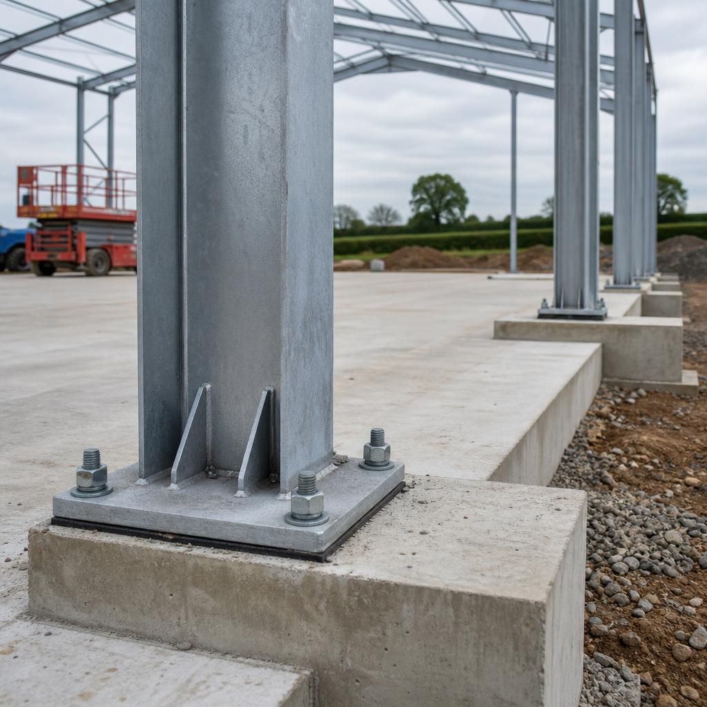
The connection between a machinery shed frame and its foundation is completed through the column base detail, not simply by placing steel onto concrete. The structural drawings should identify the base plate arrangement, anchor type, levelling method and any specified grout beneath the plate. These details allow the completed foundation to provide continuous contact and transfer the column forces as designed.
After the concrete has reached the required condition, the holding-down assemblies and foundation levels should be surveyed before the columns are installed. Any permitted adjustment must follow the engineer’s detail; drilling, cutting or forcing steelwork into position can weaken the connection or alter the intended load path. Where a levelling gap is shown, the specified structural grout should be fully packed beneath the base plate and allowed to achieve the required strength before the frame is subjected to its final loads.