
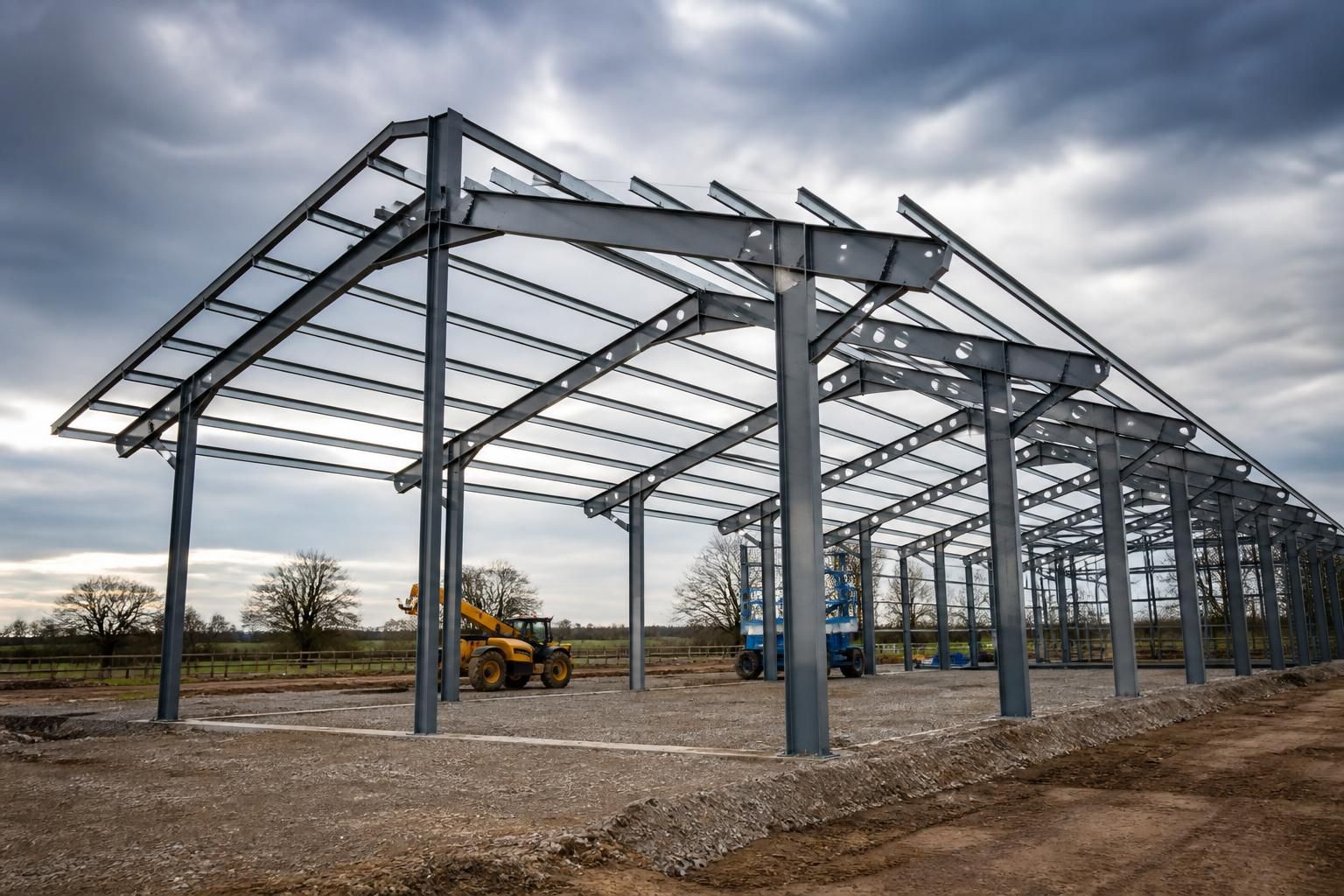
What roof loading should a machinery shed frame be designed to support?
A machinery shed frame should be designed to support its own roof weight together with the anticipated snow, wind, maintenance and any suspended equipment or storage loads. The required capacity is established through structural calculations based on the building’s dimensions, location, intended use and site conditions before fabrication.
Roof loading is the combined effect of all permanent, temporary and environmental actions that the machinery shed frame must safely transfer through the rafters, columns, connections and foundations. There is no single roof-loading value suitable for every shed: the design must reflect the proposed dimensions, roof arrangement, site exposure and the way the building will be used.
The permanent load includes the weight of the roof construction itself. This may comprise cladding, insulation, liner panels, purlins, fixings, gutters and any permanently attached services. Changing from a lightweight sheeted roof to an insulated composite system, for example, alters the load carried by the purlins and primary frame. Future additions such as solar panels, ventilation equipment or suspended lighting should be identified before the calculations are completed rather than treated as an afterthought.
Snow loading is assessed using the building’s location, altitude, roof shape, pitch and exposure. Snow can accumulate unevenly where roof slopes meet, around parapets or adjacent to higher sections, creating a localised load that is more demanding than an even covering. A machinery shed frame therefore needs to be checked for the relevant snow arrangements, including unbalanced or drifted snow where the roof geometry and surroundings make this applicable.
Wind produces both pressure and suction. The calculation considers the building’s position, height, roof profile, openings and surrounding terrain. Large doors are particularly important because opening arrangements affect internal pressure and the forces acting on the cladding and frame. Wind uplift also places demands on roof fixings, column bases, bracing and the connections between the steelwork and its supporting structure; it is not only a question of selecting heavier rafters.
Use-related loads should be described in practical terms at the design stage. Relevant information can include:
- the type and weight of any machinery, handling equipment or stored items supported by the roof;
- whether loads are distributed across the roof or introduced at specific suspension points;
- the locations of lights, ducts, fans, conveyors or other fixed equipment;
- maintenance access requirements and areas where personnel may need to work; and
- any possibility of future equipment, lining systems or internal alterations.
A distributed load and a concentrated point load affect the structure differently. A suspended item may require local strengthening to a purlin, additional connection detailing or a separate support arrangement. It should not be assumed that a standard roof member can accept a new hoist or item of plant simply because the total weight appears modest. The load path, attachment detail and any dynamic effects need to be considered together.
Structural design also checks more than ultimate strength. Excessive deflection can affect cladding, doors, gutters, seals and attached equipment even where the steel has not reached its strength limit. The frame must also have adequate lateral stability and bracing so that wind actions and temporary construction forces can be carried safely. Load combinations are then assessed so the structure is checked under the governing combinations of permanent, imposed, snow and wind actions rather than against each action in isolation.
For a reliable design, provide the building designer with the intended span, eaves and ridge arrangement, roof build-up, door positions, site details and a schedule of anything attached to or stored beneath the roof. The resulting calculations should define the design actions for the frame, purlins, connections and supporting structure. Buildings UK Ltd can incorporate these project-specific requirements into a bespoke steel building design package, helping ensure that the fabricated frame corresponds with the shed’s intended use rather than relying on an assumed generic loading.
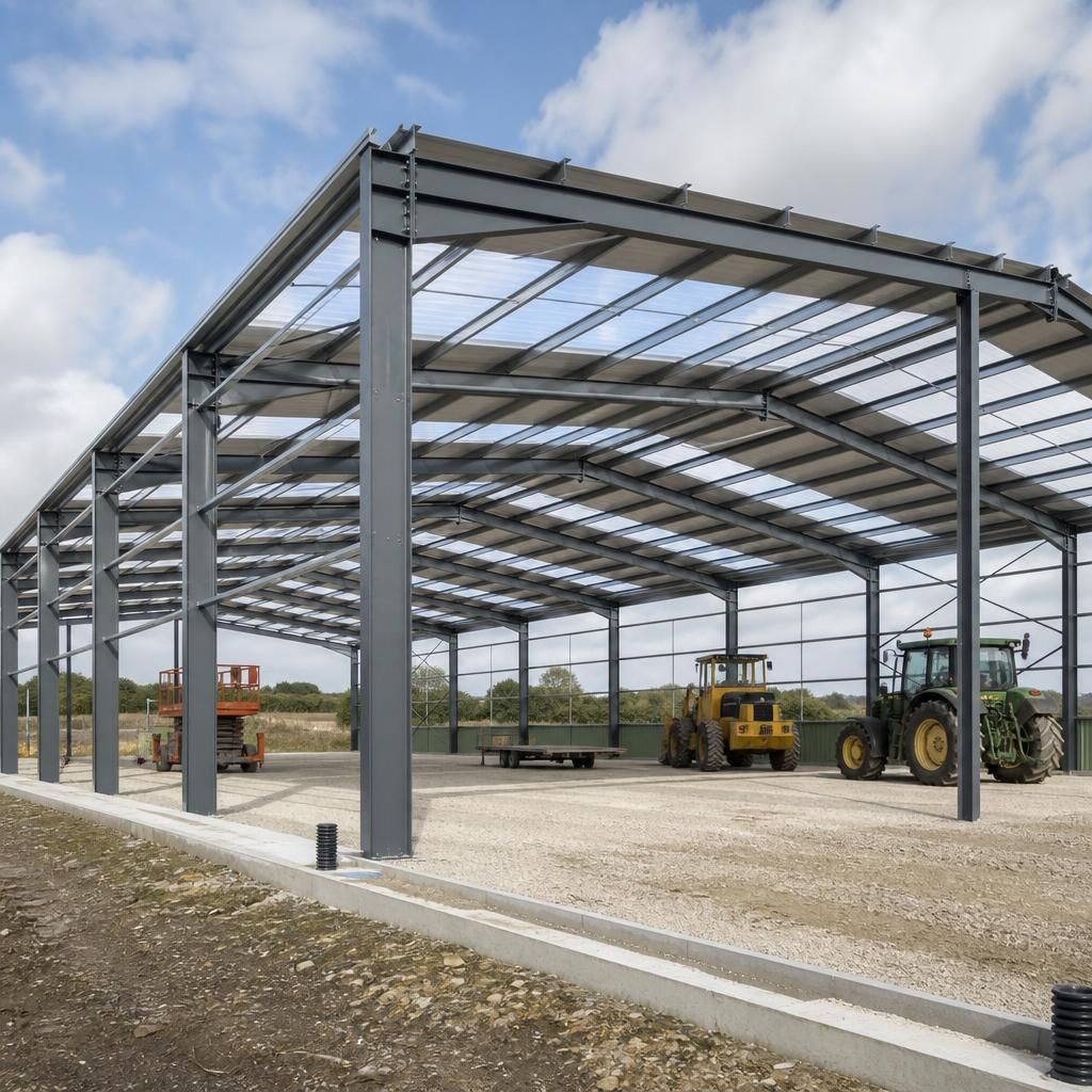
Roof cladding load tables do not define the capacity of the complete machinery shed frame. A sheet or panel may be suitable for a stated span and load, while the supporting purlins, rafters, connections and columns require separate checks. Altering purlin spacing, cladding type or fixing arrangements can therefore change the load transferred into the primary steelwork.
For this reason, roof loading should be confirmed as part of the complete structural design rather than selected from a cladding specification alone. The design information should show the assumed roof build-up, support spacing and any restrictions on attaching equipment or making later alterations, giving the installer and future users a clear basis for working within the frame’s intended capacity.
Discuss your machinery shed roof loading requirements
Discuss your machinery shed roof loading requirements with Buildings UK Ltd to establish the information needed for a project-specific steel frame design. Provide your proposed building use and any unusual loading considerations so the design brief can be assessed accurately.