
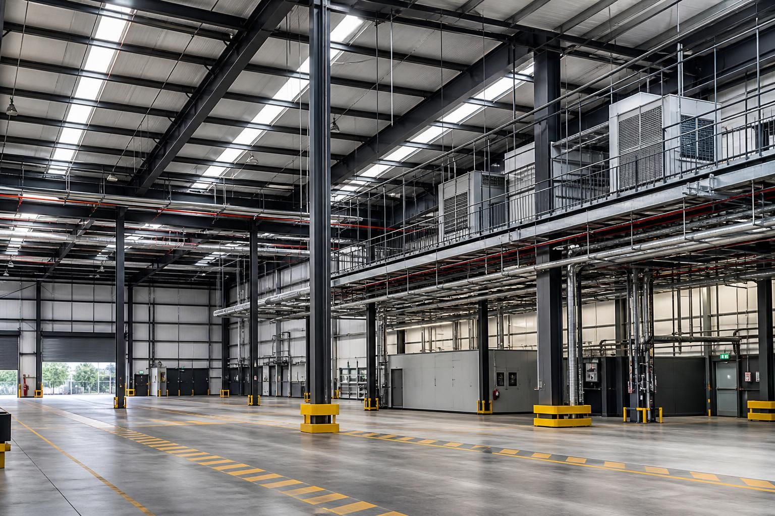
What loading requirements should a commercial steel frame building accommodate?
A commercial steel frame building should accommodate permanent dead loads, imposed floor and roof loads, wind and snow actions, and any additional loads created by its intended use. The design should also allow for equipment, storage systems, suspended services, vehicle movements and maintenance access where relevant, with load combinations assessed by a structural engineer.
Commercial steel frame building loading requirements are the calculated actions that the frame, connections, foundations and associated building elements must safely resist throughout the structure’s design life. They are determined by the building’s use, geometry, location, materials, equipment and operational arrangements, rather than by floor area alone.
Permanent actions include the self-weight of the steel frame, roof and wall construction, floors, concrete slabs, raised access floors, plant platforms and permanently fixed equipment. The design should also account for finishes, partitions, ceilings, doors, service runs and any other items that will remain in position. Allowances for future fixed installations may be appropriate where the building brief indicates that expansion or adaptation is likely.
Variable floor actions depend on how each part of the building will be occupied. An office area, warehouse, workshop, retail space and plant room will not necessarily have the same imposed loading classification. Storage areas require particular care because loading can be concentrated beneath racking legs, shelving, pallets or bins rather than distributed evenly across the floor. The design brief should identify storage heights, rack layouts, pallet arrangements and any areas where loads may be repositioned.
Where mobile plant or vehicles operate inside the building, the design may need to consider wheel loads, axle arrangements, braking, turning, impact and repeated movement. Forklift traffic can place local demands on slabs, joints, floor edges and protective barriers, while heavier vehicles may affect the supporting ground beams and foundations. Vehicle routes, loading bays, dock areas and collision-prone columns should be shown at an early stage so that structural protection can be coordinated with the frame.
Roof loading is influenced by the roof build-up, access arrangements and maintenance requirements. A roof intended only for occasional inspection differs from one supporting plant, photovoltaic equipment, walkways, ductwork or other permanent installations. Loads may be transferred through purlins, rails and local support frames, so equipment positions and access routes should be confirmed before the steelwork is detailed. Localised loads around roof openings, access hatches and plant supports also require consideration.
Snow action is affected by the site location, roof shape, pitch, height and surrounding buildings. Drifting can create uneven loading at parapets, valleys, roof steps and changes in level. The engineer should assess whether adjacent structures, taller buildings or roof-mounted obstructions could cause local accumulations. Rainwater ponding may also become relevant on low-slope roofs if drainage is restricted or deflection changes the flow path.
Wind action applies as pressure and suction to the cladding, roof and structural frame. The assessment considers the building’s location, height, dimensions, surrounding terrain and exposure, together with openings and the internal layout. Large doors, roller shutters and areas that can remain open may increase internal pressure effects. The frame, bracing, cladding rails, roof members, fixings and foundations must work together to transfer these forces safely into the ground.
Buildings containing cranes, hoists, conveyors, mixers, presses or other machinery can experience dynamic effects in addition to their static weight. Crane beams may need to resist vertical wheel loads, horizontal surge, longitudinal forces and repeated cycles. Machinery may introduce vibration or impact, requiring checks for fatigue, deflection and resonance as well as ultimate strength. The supplier’s equipment data should be incorporated into the structural brief rather than relying only on an estimated weight.
Suspended services and internal installations should be treated as structural loads where they are supported from the frame or roof. This can include lighting, sprinkler pipework, ventilation systems, cable trays, heating equipment and suspended ceilings. Their support points should be coordinated with purlins, rafters and connection details to avoid unplanned point loads or excessive local deflection. Future services should be distinguished from confirmed installations so that assumptions are clear.
Accidental and robustness considerations may be needed where there is a risk of vehicle impact, explosion, fire-related loss of capacity or the removal of a key structural element. The appropriate measures depend on the building’s use, occupancy, location and risk assessment. They can include column protection, strengthened transfer areas, alternative load paths and arrangements that limit disproportionate collapse. These provisions should be established with the project’s structural and fire engineering requirements rather than added after fabrication drawings are complete.
Loads must be combined in accordance with the applicable structural design standards and their UK National Annexes. The engineer does not simply add every possible action at its maximum value; combinations reflect which actions can reasonably occur together and include the relevant safety factors. Both ultimate limit state checks, concerned with strength and stability, and serviceability limit state checks, concerned with deflection, vibration, movement and usability, are required.
Serviceability is particularly important where the frame supports brittle finishes, large doors, cladding, glazing, cranes or sensitive equipment. Excessive movement can affect door operation, roof drainage, cladding joints and service connections even when the steel remains strong enough. Checks should therefore cover rafter and column deflection, floor vibration, sway, connection movement and the compatibility of the steel frame with slabs, walls and envelope systems.
The loading assessment should also include the construction stage. Partially completed frames may have less effective bracing, while temporary lifting operations, stored materials and erection plant can create temporary actions that do not occur in the finished building. Temporary works, sequencing and stability during erection should be addressed by the responsible design and construction teams.
A useful loading brief records the building’s location, proposed use, floor and roof build-ups, storage systems, vehicle types, machinery, crane requirements, suspended services, openings, future alterations and any unusual operational risks. It should be reviewed whenever the layout or specification changes. For a bespoke steel frame, this information enables the structural engineer to define the load paths, select suitable member sizes and connections, and coordinate the frame with foundations and other building elements before fabrication.
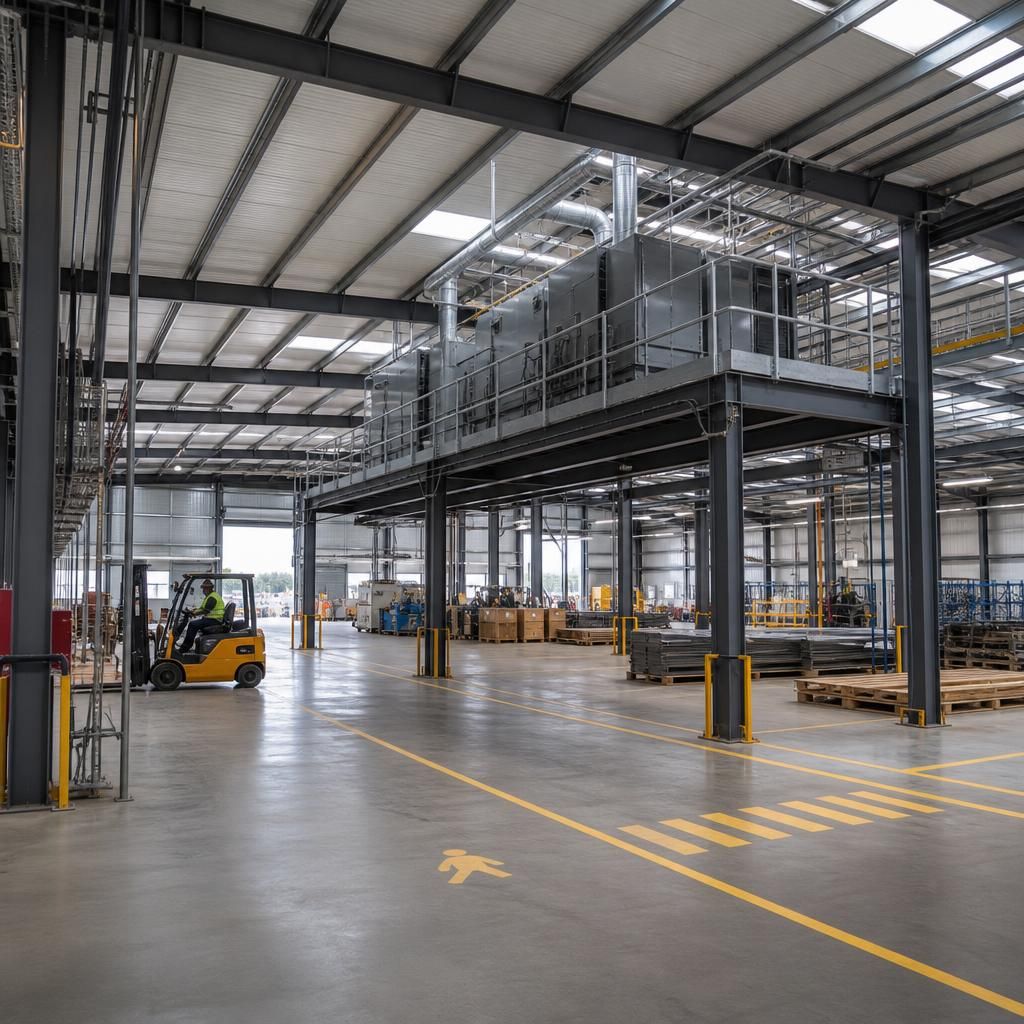
Commercial steel frame building loading requirements must be communicated to the people who will use and manage the building, not just recorded in structural calculations. Floor load limits, racking capacities, crane duties, roof access restrictions and designated storage zones should be identified where they affect safe operation.
These controls help prevent later changes from exceeding the assumptions used in design. Moving heavy equipment, adding storage, installing new plant or allowing vehicles into areas not designed for them can alter the loading pattern. Any significant operational change should therefore be checked against the original structural information before it is implemented.
Discuss your commercial steel frame building loading brief
Discuss your commercial steel frame building loading brief with Buildings UK Ltd, including the proposed use, equipment, storage arrangements and any unusual operational requirements. This provides a clear basis for coordinating the structural design with the building’s intended operation.