
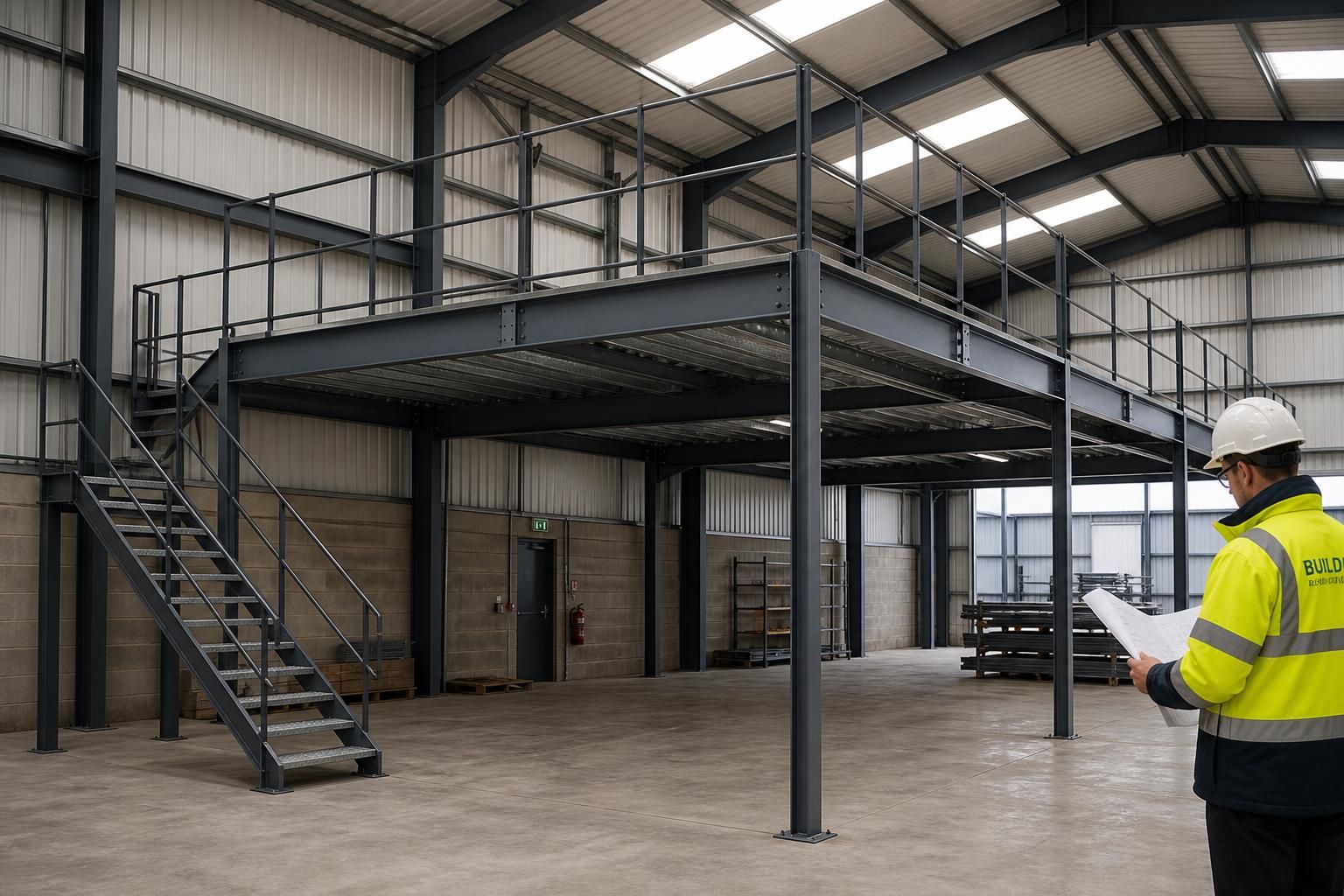
Which drawings are needed to fabricate a warehouse with mezzanine?
Fabricating a warehouse with mezzanine typically requires an approved general arrangement drawing, dimensioned plans, elevations and sections, together with detailed steelwork fabrication drawings. The package should also show member sizes, connection details, base plates, stair and guarding interfaces, floor construction, openings, levels and fixing information so the steelwork can be manufactured and installed accurately.
The drawings needed to fabricate a warehouse with a mezzanine are a coordinated set of steelwork shop drawings, supported by accurate setting-out information, connection design and specifications for materials, finishes and interfaces. Planning drawings or an architectural floor plan alone do not provide enough information for a fabricator to cut, drill, weld and prepare each component correctly.
Design and coordination information
Before fabrication drawings are produced, the design team needs to establish the information that controls the steelwork. This normally includes the building grid, structural datums, finished floor levels, surveyed site conditions and the position of any existing structure to which the new work connects. The drawing package should also identify constraints created by roller doors, loading areas, plant, services, fire escape routes and vehicle movements.
For a mezzanine, the relationship between the upper floor and the main warehouse is particularly important. The drawings must make clear where the mezzanine columns stand, how they affect storage or circulation below, and how the structure avoids clashes with doors, racking, machinery and service routes. Any information supplied by other designers should be incorporated into the coordinated model or drawing set before steelwork is released for manufacture.
Fabrication information for each steel component
Shop drawings should allow the workshop to identify every item without relying on assumptions. A complete package commonly contains:
- unique piece marks that correspond with a material list and erection information;
- member reference, section designation, overall cut length and orientation;
- plate thicknesses, profiles, notches, copes and edge treatments;
- hole positions, diameters, pitches and edge distances for bolted work;
- weld locations, weld types, sizes and whether welds are continuous or intermittent;
- fabrication tolerances and any requirements for pre-setting, camber or controlled distortion;
- material grades and traceability requirements; and
- surface preparation, galvanising, painting or other specified protective treatment.
These details are normally shown through individual assembly drawings and single-part drawings. Assembly drawings explain how several parts form a beam, column or frame, while single-part drawings provide the dimensions needed to manufacture plates, cleats, brackets and other separate items.
Connection and support information
Connections need more than a line indicating that two members meet. The relevant drawings should show the connection arrangement, fixing type, bolt and weld requirements, any stiffeners or end plates, and the tolerances needed to achieve a practical fit on site. They should also identify where forces are transferred into foundations, existing steelwork or other supporting elements.
Where connection design is carried out separately from the general structural design, the responsibilities should be recorded clearly. The fabricator should not have to decide whether a missing cleat, bolt group or stiffener is an acceptable interpretation of the design. Supporting calculations may sit behind the drawings rather than appear on every sheet, but the approved design outcome must be reflected accurately in the fabrication details.
Interface drawings
Steelwork rarely exists in isolation. The package should be checked against the items that connect to or depend on it, including concrete foundations, floor construction, edge protection, stairs, cladding, doors and building services. The drawings should identify who provides each fixing and which dimensions must be left for another trade.
For a mezzanine, particular attention is required at the upper-floor perimeter, stair openings, access points and locations where decking or a concrete topping meets the frame. If these interfaces are not resolved before manufacture, otherwise accurate steelwork may require alteration during installation.
Erection and installation information
Fabrication drawings should be supported by erection drawings showing the position and orientation of each marked item. These are not the same as workshop drawings: they guide assembly on site rather than cutting and welding in the factory. They may include frame arrangements, lifting or handling notes, temporary stability requirements, bolt installation information and the sequence in which sections are assembled.
Temporary works are especially relevant where a partially erected frame could be unstable before the mezzanine, bracing or floor system is complete. Any temporary support or erection constraint should be identified by the responsible designer or contractor rather than left to interpretation on site.
Approval, revisions and final records
Each drawing should carry a drawing number, revision, issue status, date and clear approval or review notation. A document register helps ensure that the workshop, site team and other consultants are all working from the same revision. Changes after approval should be assessed for their effect on material orders, connection design, delivery sequencing and already manufactured components.
Before release, the drawings should be checked against the design calculations, architectural information, survey data and the requirements of connected trades. After installation, an updated record may be prepared to show approved site changes, although this is a project record rather than a substitute for the fabrication package.
Buildings UK Ltd provides bespoke design packages that can include planning information and isometric fabrication blueprints. For a warehouse mezzanine, the important point is that the final steelwork information is sufficiently detailed, coordinated and approved for the exact structure being manufactured and installed.
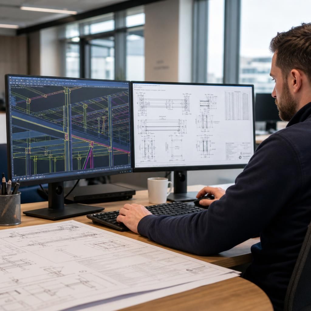
A fabrication drawing must be unambiguous at workshop level: each component should be identifiable from stated dimensions and notes, without relying on scale measurements or assumptions. It should show the drawing units, reference points, orientations and any relevant tolerances so that the intended geometry can be checked before cutting or assembly.
- Use clear section and elevation references for complex members.
- Distinguish holes, slots, welds and site-installed fixings using consistent symbols and notes.
- Identify which dimensions control the finished position and which are derived.
- Record any required checks before dispatch, such as trial assembly or inspection of critical connections.
This level of clarity helps separate workshop work from site work and reduces the risk of a correctly manufactured component being installed in the wrong orientation or position.