
What drawings are provided for an industrial metal building?
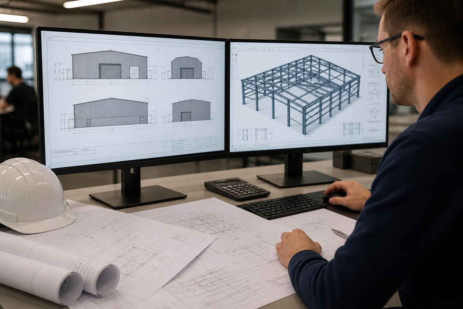
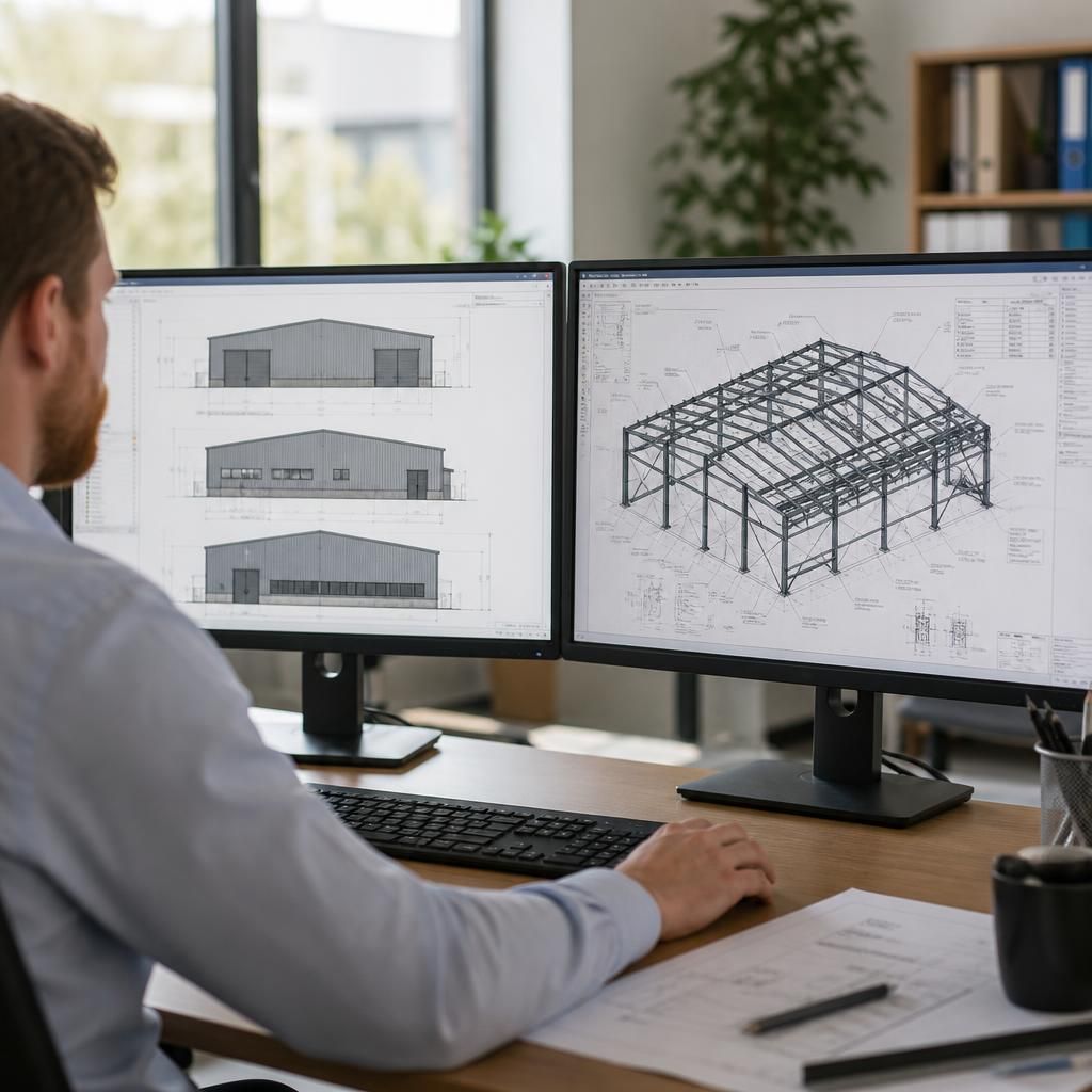
Industrial metal building drawing packages typically include planning elevation drawings and detailed isometric fabrication blueprints. These drawings show the building’s proposed appearance and provide the precise information needed to manufacture and assemble its hot rolled steel frame.
The drawing package is generally split between information for planning and information for manufacture and assembly. Planning elevation drawings communicate the proposed external form of the building, while the detailed isometric fabrication blueprints translate the agreed design into instructions for producing and putting together the steel frame.
Planning elevation drawings are intended to show how the industrial building will appear from each relevant side. They can set out the building’s overall proportions, roof arrangement, wall lines, openings and principal dimensions. This gives a planning authority, architect or project team a clear reference for assessing the proposed development without needing to interpret the steelwork in manufacturing detail.
These drawings are also useful for checking the design before fabrication begins. They allow the project team to compare the proposed elevations with the site layout, confirm the position and size of doors or other openings, and identify changes to the building’s external arrangement at an early stage. Any planning conditions or design amendments should be reviewed against the current drawing revision rather than an earlier issue.
Isometric fabrication blueprints provide the three-dimensional information needed to understand how the hot rolled steel frame is formed. Depending on the agreed design, this information can show the relationship between the main frame members, secondary steelwork, connection points, plates, openings and relevant dimensions. The isometric view helps the fabricator and erector understand how individual components relate to one another in the completed frame.
Fabrication information needs to be read as a coordinated set. Important points to check include:
- the building length, width, height and roof geometry;
- frame positions and the sequence of bays;
- the location of openings and areas where the frame must accommodate them;
- member identification and the relationship between primary and secondary steelwork;
- connection details and fixing information where included; and
- drawing revisions, dimensions and notes that have been updated following design changes.
The two drawing types serve different purposes and should not be treated as interchangeable. An elevation can confirm the intended appearance but normally does not contain all the information required to manufacture every steel component. Conversely, an isometric fabrication blueprint is concerned with accurate production and assembly, rather than presenting the building in the simplified format normally used for planning review.
For a bespoke project, the drawings should be checked against the practical requirements of the site and the intended use of the building before approval. This includes confirming the required clearances, access openings, internal layout constraints and any interfaces with foundations, cladding or other elements designed by separate parties. Where another professional is responsible for foundations, building services or specialist equipment, the steelwork information should be coordinated with that work before manufacture.
The final content can vary with the building’s size, configuration and scope of supply. A kit-only project may require the steelwork information to be used alongside separate site and foundation details, whereas a project involving erection will need the fabrication information to be suitable for coordinating assembly on site. The current issue of the bespoke drawing package is therefore the key reference for confirming what is included in a particular industrial metal building project.
Industrial metal building drawings do not always represent the complete project documentation. The core package covers planning elevations and hot rolled steel fabrication information, while documents for foundations, site setting-out, cladding, doors, services or specialist equipment may fall within separate design responsibilities.
Before approving the package, confirm which interfaces are shown and which must be developed by others. In particular, check that the information gives the foundation designer the required support positions and levels, and that openings and fixing zones are understood by whoever is detailing the building envelope. This avoids treating the steel frame drawings as a substitute for every drawing needed to construct the finished building.