
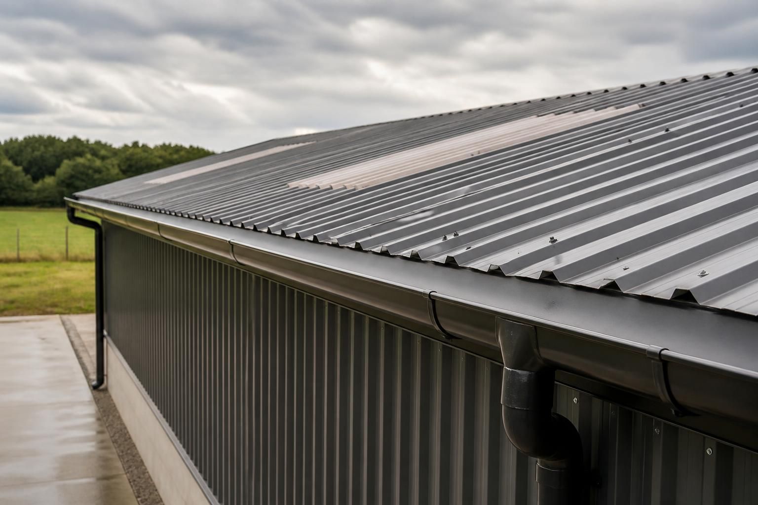
How should drainage be designed for metal roofing sheets?
Effective drainage for metal roofing sheets combines a suitable roof fall with correctly sized gutters, outlets and downpipes based on the roof area and local rainfall conditions. Sheets should be detailed at eaves, verges, valleys and penetrations so water is directed into the drainage system without ponding, backflow or exposure of vulnerable laps.
Drainage for metal roofing sheets should be designed as a complete rainwater system, taking water from the sheet surface to a suitable discharge point without relying on exposed laps, sealants or uncontrolled overflows. The design must account for the roof geometry, catchment area, rainfall intensity, sheet profile, gutter arrangement, outlet capacity and the consequences of water escaping onto walls, doors, stored materials or adjacent ground.
The roof plan should be established before the drainage components are selected. Identify each roof slope, eaves line, valley, parapet, abutment and roof penetration, then determine where water will naturally collect. A simple single-slope roof may discharge to one eaves gutter, whereas a duo-pitch or multi-bay building may require separate gutter runs, valley gutters and several downpipe positions. Dividing a large roof into manageable drainage zones helps prevent excessive flow being concentrated at one outlet.
Roof falls should be maintained consistently towards the intended drainage edge. Local depressions in the supporting steelwork or purlins can create ponding even where the overall roof has a fall. Ponded water increases the load on the sheets and supporting structure, encourages dirt accumulation and can test the performance of laps, fixings and penetrations. The supporting frame, purlin layout and sheet installation tolerances should therefore be coordinated so that the finished roof drains as designed.
Gutters need enough cross-sectional capacity for the water delivered by the roof, with sufficient freeboard to reduce the risk of spilling during intense rainfall. Their width, depth and shape should be considered alongside the roof edge detail rather than treated as an afterthought. A gutter that is too small, poorly aligned or installed with inadequate fall can overflow even when the roofing sheets themselves are correctly fixed.
- Allow for the full roof catchment entering each gutter section, including water redirected from adjoining slopes.
- Position gutters so that the sheet overhang discharges centrally into the channel rather than behind it or over its outer edge.
- Provide a continuous, properly supported gutter edge where snow, maintenance loads or thermal movement could affect alignment.
- Detail joints, stop ends and corners to accommodate movement and to avoid depending solely on mastic for long-term watertightness.
- Use access points or removable components where gutters and outlets will need inspection or cleaning.
Downpipes should be distributed according to the flow reaching each gutter section, not simply placed at convenient corners. Long gutter runs may need additional outlets to limit the volume travelling along the channel. Outlet shape, pipe diameter, bends and discharge restrictions all affect the system’s effective capacity. Sharp changes of direction can slow flow and increase the chance of blockage, so the route should be kept as direct as the building layout permits.
Every low point requires a deliberate overflow strategy. An outlet blockage, frozen discharge route or unusually heavy rainfall should not leave water with nowhere to go. Overflow provision may take the form of a visible discharge path, a raised gutter arrangement or a separate emergency outlet, depending on the building design. The chosen route should prevent water from being trapped beneath the sheets or directed into the building envelope. It should also make a problem apparent during inspection rather than allowing hidden deterioration to continue.
Valleys require particular attention because they receive water from two roof planes and may also collect leaves, silt and debris. The valley width, depth, fall and side-lap detailing must work with the profile of the metal sheets. Cut sheet edges should be supported and protected, and the valley should not be narrowed by fixings, sealant or poorly positioned closures. At roof-to-wall abutments, stepped or continuous flashing should direct water onto the roof drainage path while preserving movement between dissimilar materials.
Eaves details should prevent wind-driven rain from passing behind the gutter or entering the roof build-up. Closures and flashings need to suit the sheet profile, while the sheet overhang must be consistent along the run. At verges, water should be kept away from exposed edges and the supporting wall. Penetrations such as vents, flues and rooflights should have upstand and flashing details that shed water around the obstruction and back onto the sheet surface or into a designed channel.
The discharge point is part of the drainage design, not merely a final connection. Downpipes may discharge into surface-water drainage, attenuation, soakaway arrangements or controlled ground-level outlets, subject to the site’s conditions and applicable requirements. Consider the ground profile, proximity of foundations, service routes, hardstanding and areas where runoff could create erosion or standing water. Where a building is on a sloping site, drainage from the higher side may need to be intercepted so it does not overload the roof drainage or flow towards entrances.
Material compatibility is also important. Gutters, fixings, flashings and roofing sheets should be selected so that contact with one another does not create an avoidable corrosion risk. Runoff from one metal can affect another, particularly where dissimilar materials remain wet for extended periods. Cut edges, drilled swarf and trapped debris should be removed during installation, since contamination can obstruct outlets and accelerate local corrosion.
Drainage drawings should show falls, gutter sizes, outlet locations, downpipe routes, overflow arrangements and discharge points, together with critical eaves, valley, verge and penetration sections. These details allow the steel frame, cladding package and ground drainage works to be checked as one coordinated system. Before handover, gutters and valleys should be cleared of swarf and construction debris, outlets checked for free flow and all visible flashings and joints inspected. A planned inspection and cleaning routine is particularly important for agricultural and industrial buildings near trees, dusty processes or loose material.
For a bespoke metal-framed building, drainage design is best reviewed alongside the roof structure and fabrication drawings. This helps ensure that purlins, eaves members, openings and rainwater components do not conflict, and that the finished arrangement can be installed and maintained without compromising the roof covering.
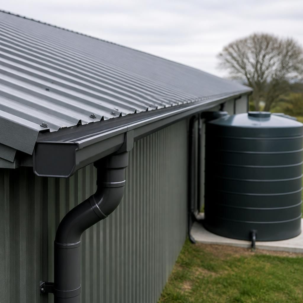
Where rainwater is being collected for reuse, the roof drainage system should be designed for both conveyance and storage. Gutters and downpipes must deliver runoff to the tank without creating backflow, while the tank requires a screened inlet, a suitable overflow and a discharge route for periods when storage is full. The overflow should remain independent of the roof covering so excess water cannot track beneath the metal roofing sheets.
Runoff intended for collection should also be kept separate from contaminated areas, such as vehicle wash points or locations where agricultural chemicals, oils or process residues may enter the drainage path. Access for cleaning filters and inspecting tank connections should be included in the layout. This approach makes rainwater harvesting part of the overall roof drainage design rather than an attachment added after the gutters and downpipes have been positioned.