
How should roof cladding systems be detailed for water drainage?
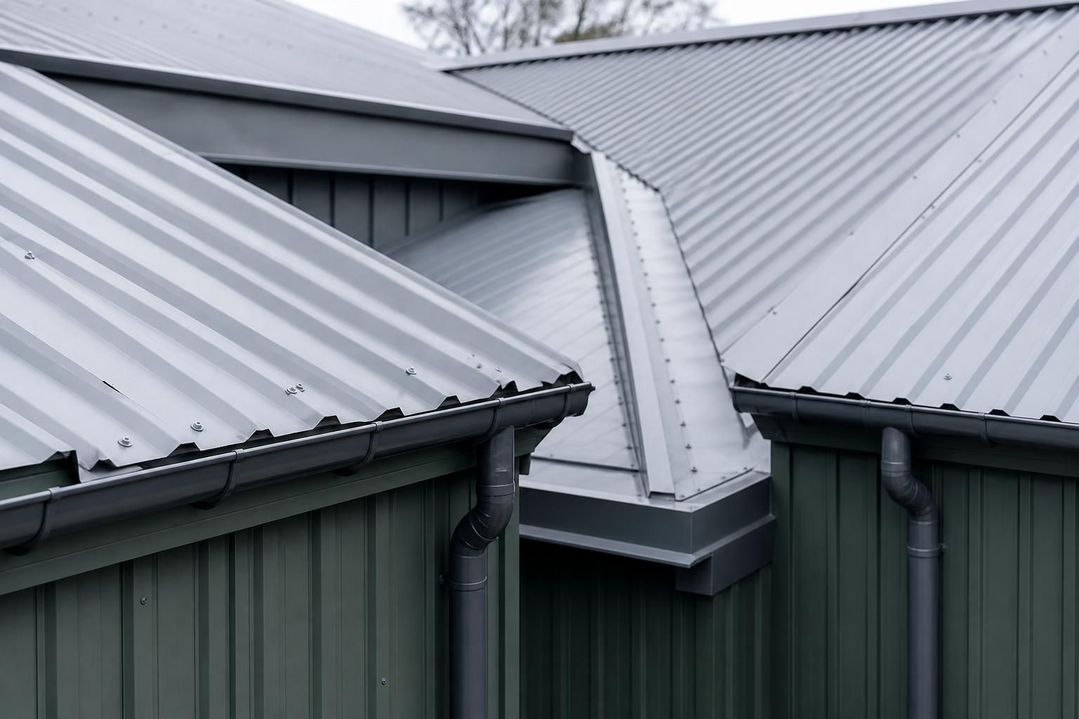
Roof cladding systems should be detailed with continuous falls towards correctly sized gutters, outlets or other controlled discharge points, avoiding low spots where water can pond. Laps, penetrations, abutments and edge details must be weather-sealed and arranged so that drainage paths remain unobstructed.
Effective water drainage from a roof cladding system depends on coordinated falls, hydraulic capacity, weathered junctions and safe discharge. The design should show how rainwater travels from each roof area into gutters, valleys, outlets and downpipes, while allowing for tolerances, deflection, overflow conditions and future maintenance.
Drainage design should begin with the roof plan and the rainfall data applicable to the site. The expected rainfall intensity, catchment area and roof geometry determine the volume of water requiring removal. Gutters, outlets and downpipes must then be sized as a system rather than selected independently. The design should account for water received from adjoining roof slopes, parapets, canopies and roof-mounted features, as these can increase the effective catchment.
- Gutters: provide sufficient cross-sectional capacity and a suitable longitudinal fall towards the outlets. Their profile should be compatible with the cladding edge and supported against distortion.
- Outlets: position them where water naturally collects, with outlet connections sized to avoid restricting the gutter above.
- Downpipes: align them with the discharge route and ensure that their lower connections can accept the anticipated flow without backing up.
- Valleys: detail them with adequate width, support and unobstructed flow, particularly where two roof slopes concentrate water in one location.
The roof structure and cladding support must retain the intended drainage geometry under imposed loads. Structural deflection, accumulated rainwater and installation tolerances can reduce a designed fall or create local changes in level. Details should therefore consider the behaviour of purlins, rails, decking, liner systems and gutter supports, rather than relying on the nominal roof pitch alone. Where ponding could increase loading, the structural and drainage designs need to be reviewed together.
Every change in direction or level requires a deliberate weathering detail. Eaves, verges, ridges, valleys, parapets, rooflights and abutments should direct water over or into the drainage system without allowing it to run behind flashings or into the building fabric. End laps and side laps should be arranged so that water follows the intended drainage direction, with fixings, sealants and closures located in accordance with the cladding system design. Sealants should not be used as a substitute for a sound overlap or positive water-shedding arrangement.
Penetrations for ducts, pipes, plant supports and access equipment should be kept away from drainage channels where practicable. Each penetration needs a raised, weathered upstand or proprietary flashing arrangement that remains compatible with the roof profile and cladding movement. The detail should prevent water from being trapped on the uphill side and should preserve access for inspection without damaging the weathering layer.
Overflow provision is an important part of the drainage strategy. If an outlet or downpipe becomes blocked, the roof should not discharge uncontrolled into the building. External gutters may require visible overflow routes, while internal gutters, valleys and concealed drainage zones generally need secondary outlets or high-level overflow details. Overflow openings should be placed so that failure is apparent and water is directed away from sensitive construction and occupied areas.
Where internal gutters or outlets are used, the surrounding construction should be designed for the consequences of leakage as well as normal operation. Waterproof liners, upstands, joints and penetrations need a continuous, inspectable arrangement. Access panels or removable sections may be necessary so that outlets, leaf guards and joints can be checked without dismantling extensive areas of cladding.
Condensation control should be kept distinct from rainwater drainage. A liner or vapour control layer may manage internal moisture, but it does not replace the external weathering and drainage design. Similarly, an apparent leak may originate from a failed lap, flashing or penetration rather than from an undersized gutter. The specification and inspection process should identify these functions separately.
Drainage drawings should show roof falls, catchment boundaries, gutter and valley routes, outlet locations, overflow paths, downpipe positions and all interfaces with adjacent construction. Sections are particularly useful at eaves, valleys, parapets and roof penetrations because they reveal whether laps, closures, upstands and discharge points remain workable after installation. Fabrication and installation drawings should match the drainage design so that support members, fasteners and flashings do not obstruct the intended flow.
Finally, the completed system needs a maintainable drainage route. Gutters, outlets and valley areas should be accessible for removal of leaves, silt and other debris, with guards used only where they do not reduce effective capacity or make cleaning impractical. Handover information should identify drainage components and inspection requirements, allowing blockages, displaced flashings, damaged seals and signs of ponding to be addressed before they cause more extensive deterioration.
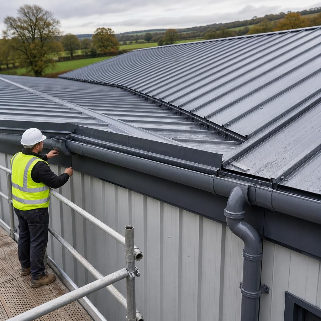
Roof drainage detailing must continue beyond the gutter and downpipe to the point where rainwater is safely released. Downpipe shoes, gullies or connections to below-ground drainage should be coordinated with paving, thresholds and the building’s base detail so that water cannot collect against the wall or splash back onto cladding.
Where rainwater is discharged above ground, the outlet should be positioned to prevent erosion and staining, while allowing the connection to be inspected and cleared. The drainage drawings should identify the final discharge route, not stop at the downpipe, so that roof water does not undermine foundations, saturate adjoining ground or enter service openings.