
What wall build-up is compatible with an SFS cladding system?
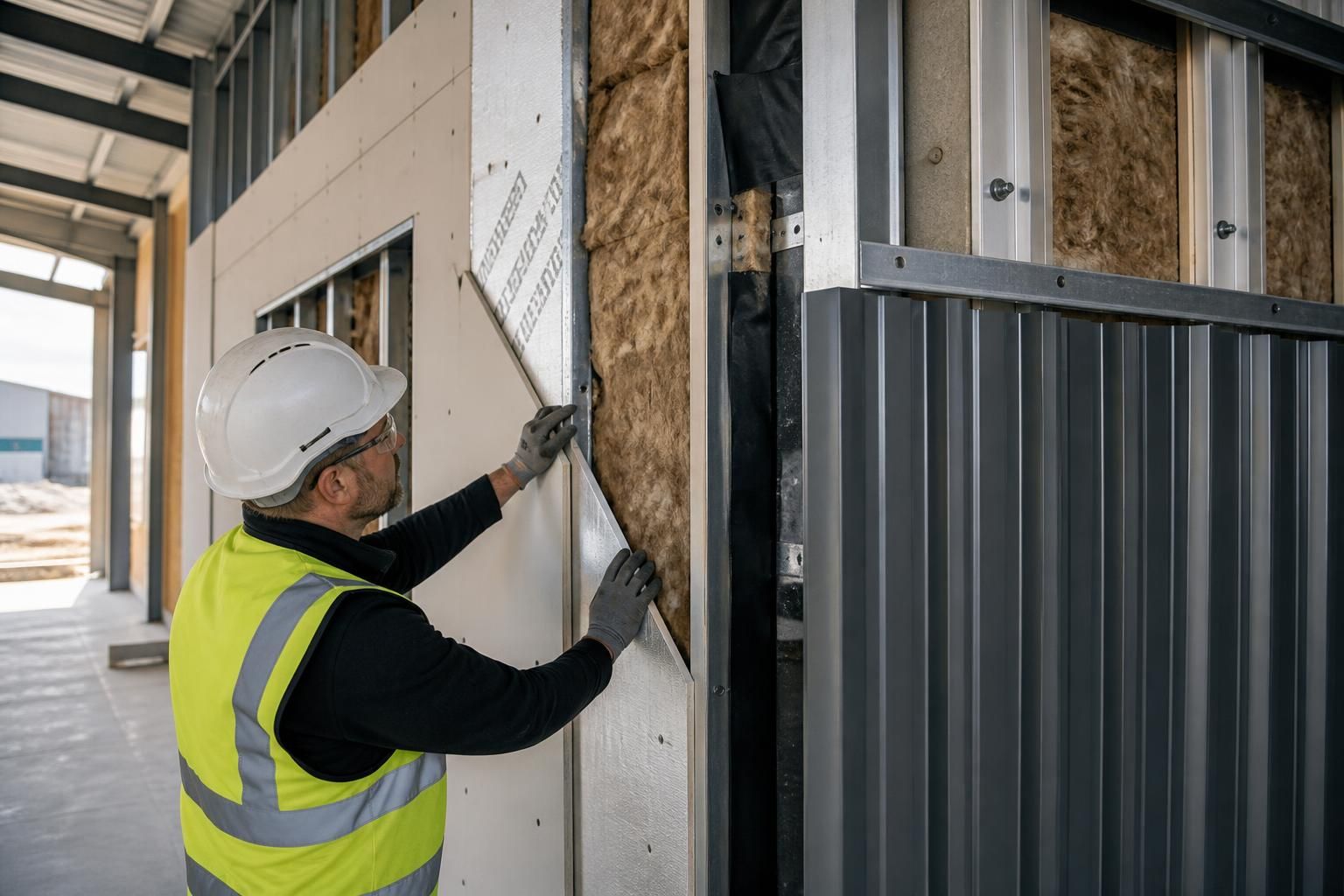
An SFS cladding system is typically compatible with a layered wall build-up comprising external cladding, a drained and ventilated cavity, sheathing, insulation, a vapour control layer and an internal lining. The precise arrangement depends on the required thermal, moisture, fire and structural performance, so each layer and its interfaces should be coordinated during design.
A compatible SFS wall build-up is one in which the framing, sheathing, insulation, membranes, cladding and internal lining work together as a complete structural and environmental system. The selected arrangement must transfer wind and imposed loads safely, control rainwater and condensation, provide the required thermal and fire performance, and accommodate movement at joints, openings and changes in materials.
The external finish can vary considerably. Common options include:
- Profiled steel sheeting: typically fixed to suitable rails or supports, with the cavity and support arrangement allowing drainage and ventilation behind the sheets.
- Rainscreen cladding: metal, fibre cement or other panel systems can be mounted on a carrier system, provided the brackets and rails are designed for the loads and keep the cavity continuous.
- Insulated composite panels: these may combine weather protection and insulation in one product, but the panel joints, fasteners, fire performance and junctions with the SFS frame require specific coordination.
- Brick slips or lightweight masonry finishes: these need an appropriate carrier, restraint and support detail. They should not be treated as a direct substitute for a self-supporting masonry outer leaf.
The SFS studs usually receive sheathing on the external face. Its function may include providing racking resistance, supporting membranes and forming a suitable substrate for the chosen external system. The sheathing specification should therefore be selected alongside the structural design rather than as an isolated lining choice. Board type, thickness, fixing pattern and joint treatment can all affect the wall’s performance.
Insulation can be arranged between the SFS studs, outside the sheathing, or in a combination of both positions. Insulation between studs makes efficient use of the frame depth, while a continuous external layer can reduce thermal bridging through the steel members. Where both are used, the proportions and continuity of the layers need to be checked as part of the thermal and condensation assessment. Gaps around the perimeter of openings, at floor zones and at junctions with the roof or foundations should be avoided.
Membranes are selected according to their position and purpose. An external breather membrane may protect the sheathing and insulation from wind-driven rain while allowing water vapour to escape towards the ventilated cavity. On the internal side, a vapour control and airtightness layer is normally positioned towards the warm side of the insulation. Its laps, penetrations and connections to floors, roofs, windows and doors are as important as the membrane itself. A build-up that appears suitable in section can perform poorly if these interfaces are left unresolved.
The cavity behind the external cladding must have a defined drainage route. Flashings, cavity trays, seals, weep arrangements and ventilation openings should direct water away from the SFS frame and prevent it from being trapped at the base or around openings. The cavity depth and support system also need to suit the cladding manufacturer’s installation requirements, while fire-stopping should be incorporated where cavity barriers are required.
On the internal face, the lining may comprise one or more layers of plasterboard, a higher-impact board, a cement-based board or an internal liner system. The appropriate choice depends on the required fire resistance, acoustic separation, moisture exposure, durability and fixing capacity. Heavy fixtures, machinery restraints, shelving and agricultural or industrial equipment may require additional noggins, backing plates or independent support rather than relying on the lining alone.
Fire design must consider the complete wall rather than individual products. The SFS studs, sheathing, insulation, membranes, cavity barriers, cladding and internal boards can all influence the result. Particular attention is needed at compartment lines, around service penetrations and where the wall meets floors, roofs or fire-resisting elements. A tested or assessed build-up should be followed without unapproved substitutions, because changing one layer can affect the performance of the whole assembly.
Structural compatibility also depends on how the wall is used. A non-loadbearing SFS infill wall may be designed to accommodate movement of the primary frame, whereas a structural wall may carry roof, floor or cladding loads. The design must establish the required stud gauge and spacing, bridging, restraint, deflection allowance and fixing capacity. Cladding weight, wind pressure, suction, snow-related attachments and loads around doors or windows should be included where applicable.
Windows, personnel doors, roller shutters and large vehicle openings often determine the practical wall detail. They may require strengthened jambs, lintels, additional sheathing, carefully formed cavity closers and continuous membrane connections. At the base of the wall, the SFS frame should be separated from ground moisture and coordinated with the slab, threshold, damp-proof course and external paving levels. At the roof, the wall must connect cleanly to the roof insulation, eaves closure and weathering details.
For agricultural and industrial buildings, the internal environment also affects material selection. High humidity, wash-down conditions, chemical exposure, dust or corrosive atmospheres can influence the choice of cladding finish, fasteners, internal lining and protective coatings. In such settings, a nominally compatible wall may still be unsuitable if its materials do not match the building’s exposure conditions.
The final build-up should be checked as a coordinated design package covering structural adequacy, U-value and thermal bridging, condensation risk, airtightness, fire, acoustics, weathering and installation tolerances. Planning elevations show the external appearance, while detailed sections and fabrication information should resolve the layer sequence, fixings and junctions. This coordination is what makes a chosen cladding arrangement genuinely compatible with the SFS frame.
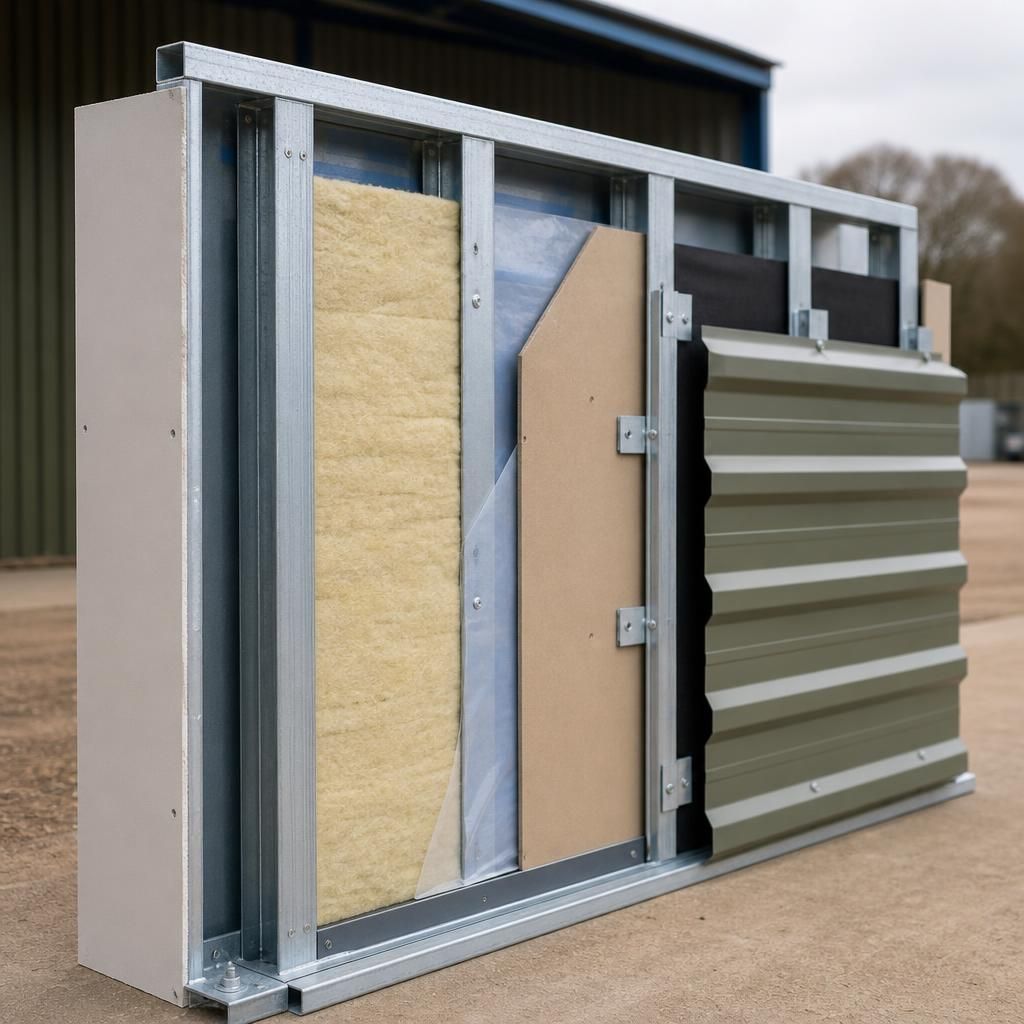
Compatibility also depends on how the wall build-up will be installed. The SFS frame, sheathing, membranes and cladding supports must leave enough room for board joints, fastener access, drainage paths and adjustment at irregularities in the primary structure. A theoretically suitable layer sequence can become impractical if one component prevents the next trade from forming a continuous or secure connection.
Before selecting the final arrangement, review the interfaces in installation order. Confirm that:
- the cladding support can be fixed without compromising the sheathing or membranes;
- board edges and joints have the specified support;
- membranes can be lapped and sealed at corners, openings and penetrations;
- the cavity remains clear after rails, brackets and fire-stopping are installed; and
- tolerances allow the external finish and internal lining to be set out accurately.
This interface review is particularly important where different systems meet, such as at window reveals, parapets, corners and changes from one cladding type to another.
Plan Your Compatible SFS Wall Build-Up
Share your proposed building use, external finish and performance requirements with Buildings UK Ltd to review the most suitable SFS wall build-up and its key junctions. Their bespoke design service can then develop the coordinated drawings and fabrication information needed for the project.