
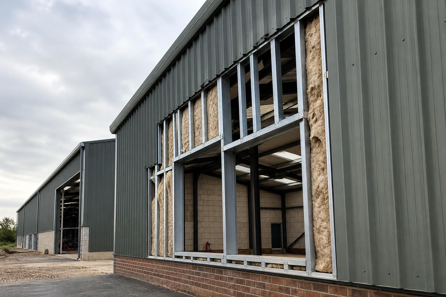
Which design priorities support choosing an SFS cladding system?
Choosing an SFS cladding system should be guided by the building’s structural, thermal, acoustic, fire and moisture-control requirements, alongside the intended cladding finish. Design coordination, durability, compliance and practical installation should also be assessed so the system performs as part of the complete wall construction.
The key design priorities for an SFS cladding system are a clearly defined load path, coordinated interfaces with the primary structure, allowance for movement, buildable detailing and a specification that remains suitable throughout the building’s intended service life. SFS should therefore be developed as part of the complete building envelope rather than selected as an isolated wall component.
Establish the load path first. The design should show how the external cladding loads are transferred through the rails, studs, tracks, fixings and brackets into the primary frame or supporting structure. Wind actions, the weight of the cladding build-up and forces around openings all need to be considered. The support arrangement should also identify where concentrated loads occur, such as at corners, parapets, door openings and changes in cladding direction. This avoids relying on adjacent components to perform a structural function for which they were not designed.
Coordinate the SFS frame with the primary structure. Steel columns, beams and slab edges rarely form a perfectly uninterrupted line. An SFS layout must accommodate changes in grid, deflection zones, connections and variations in edge conditions. Brackets, cleats and other interface details should be agreed before fabrication so that the secondary frame can be installed without cutting or adapting members on site. For industrial and agricultural buildings, this coordination is particularly relevant around large openings, eaves, gables and areas where the wall meets a portal frame.
Allow for movement and tolerance. Primary steelwork can deflect under load, while temperature changes and moisture-related movement can affect adjoining materials. SFS connections should be detailed so that expected movement does not transfer damaging forces into the cladding, linings or finishes. Slotted connections, movement joints and deflection allowances may be appropriate, depending on the building form and the manufacturer’s system requirements. The design should also account for reasonable fabrication and erection tolerances, with clear adjustment provisions where the frame meets existing or irregular construction.
Resolve openings and penetrations early. Windows, personnel doors, roller shutters, loading doors, vents, louvres and service penetrations interrupt the regular stud arrangement. Each opening may require additional framing, support to its perimeter and a carefully coordinated method of connecting the surrounding cladding. Large industrial openings can influence the stiffness and fixing pattern of the adjacent wall, so they should not be treated as simple gaps in an otherwise standard layout. Mechanical and electrical penetrations should likewise be located before the frame and sheathing details are finalised.
Make the interfaces unambiguous. The most vulnerable parts of an SFS wall are often the junctions: base of wall, roof edge, corners, parapets, movement joints, window surrounds and changes between cladding materials. Drawings should show the continuity of support, weathering layers, flashings, cavity barriers and seals at each junction. A detail that works on the main wall elevation may not work at a corner or opening, where water paths, fixings and tolerances change.
Design for an achievable installation sequence. The order of work affects whether the system can be aligned, inspected and protected properly. The design should identify temporary stability requirements, the sequence for installing framing and sheathing, and when membranes, insulation and external cladding can be added. Materials should be accessible for fixing without forcing installers to work around completed services or finishes. Clear member marks, setting-out information and fabrication drawings can reduce uncertainty during erection.
Consider maintenance and future alterations. The selected arrangement should allow damaged panels, flashings and trims to be replaced without unnecessary disturbance to the rest of the wall. Areas exposed to impact from vehicles, agricultural equipment or internal operations may need more robust protection and a practical repair strategy. If the building may later receive additional doors, ventilation equipment or internal partitions, the likely alteration zones should be considered during the initial structural layout.
Check the design against the building’s use. An SFS wall for an agricultural building may face different exposure, impact and wash-down conditions from a wall serving an industrial or commercial space. Internal operations, vehicle movements, stored materials and the position of equipment can affect the required protection and detailing. The design should distinguish between normal wall loading and accidental or operational impacts, rather than applying one generic arrangement to every elevation.
Keep the documentation coordinated. The design package should bring together setting-out drawings, connection details, opening schedules, cladding information and fabrication drawings. Revisions to the primary frame, openings or service routes need to be reflected consistently across these documents. For a bespoke steel-framed building, planning elevation drawings and isometric fabrication blueprints provide useful coordination information when they accurately show how the SFS and cladding relate to the wider structure.
In practice, the strongest SFS specification is one that can be traced from design assumptions through to individual connections and installation details. Reviewing structural interfaces, movement, openings, sequencing and maintenance before manufacture helps ensure that the cladding system is not only suitable in principle but also practical to fabricate, erect and manage over the building’s working life.
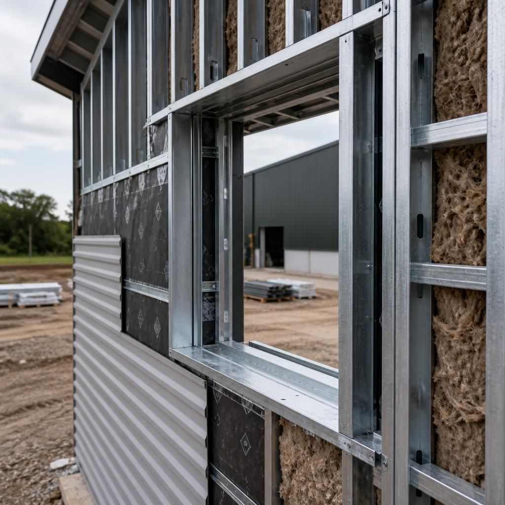
Performance requirements should be defined before selecting the SFS arrangement, because the steel frame is only one part of the wall’s overall behaviour. The specification should coordinate insulation, sheathing, membranes, cavity barriers, internal linings and external cladding to achieve the required thermal, acoustic, fire and moisture-control performance.
Particular attention is needed at junctions, openings and service penetrations, where gaps or discontinuous layers can undermine the intended result. The proposed build-up should be checked against the project’s regulatory requirements and the building’s use, exposure and internal conditions. This approach helps ensure that the SFS system is selected as part of a compliant wall assembly rather than judged on framing capacity alone.