
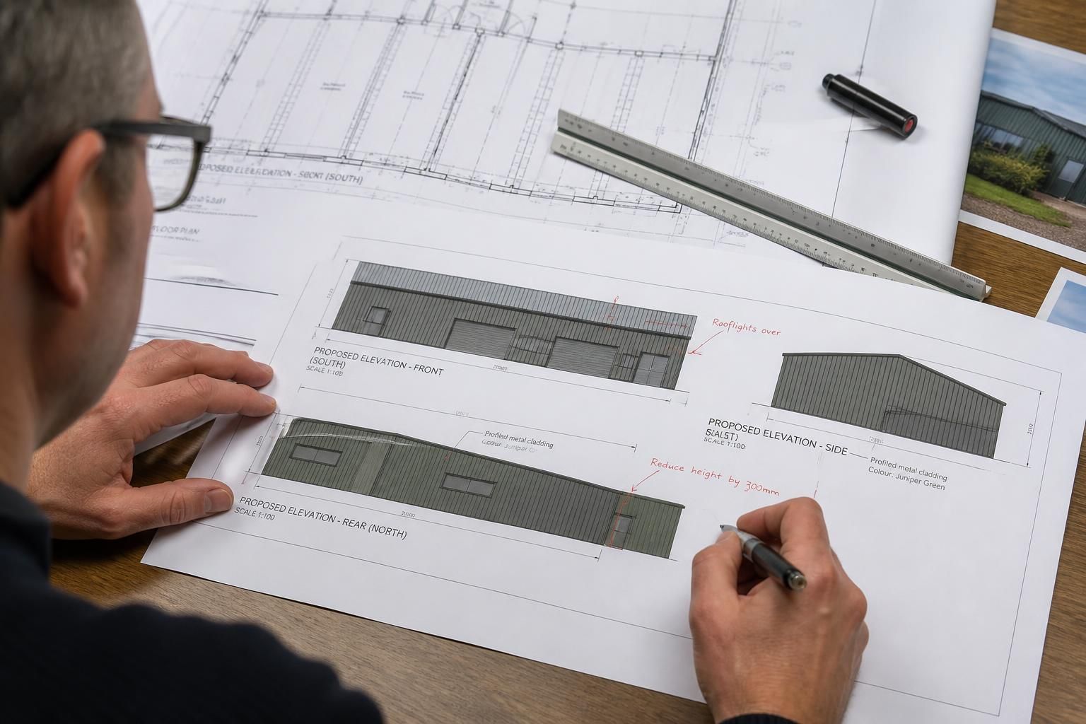
What planning drawings are needed for steel roofing and cladding?
Planning applications for steel roofing and cladding commonly need a location plan, block plan and existing and proposed elevation drawings showing the building’s position, dimensions, roof profile, materials and cladding finish. Depending on the project, floor plans and cross-sections may also be required to explain height, construction and how the proposed work relates to the existing structure.
Planning drawings for steel roofing and cladding are the visual evidence used by a local planning authority to assess the building’s appearance, scale, position and effect on its surroundings. The exact package depends on whether the work is a new building, an extension, a replacement roof or cladding over an existing structure, and on the requirements of the relevant authority.
Start by establishing the scope of the application. A like-for-like replacement may require less explanation than a proposal that changes the roof pitch, increases the height, extends the footprint or changes the external appearance. New cladding can also be a material change when it alters the character of a building or its relationship with neighbouring land. The drawings should make clear which parts are existing, which are to be removed and which are proposed.
A complete drawing set commonly includes the following supporting information:
- A location plan identifying the site in relation to surrounding roads, buildings and land. This establishes where the property is situated.
- A block plan or site plan showing the application boundary, access, nearby structures, hardstanding, parking, landscaping and relevant site features. For agricultural or industrial premises, the relationship with yards, storage areas and other buildings may be particularly important.
- Existing and proposed roof plans where the roof form, coverage, drainage arrangement or roof-mounted features are changing. These can show the direction of the roof slopes, ridges, valleys, rooflights, vents and other visible elements.
- Existing and proposed elevations for every affected face. These should identify the finished appearance, openings, roof edges, gutters, downpipes, cladding direction and the materials or finishes proposed.
- Sections or construction profiles where the authority needs to understand the relationship between floor level, eaves, ridge, roof build-up, wall height and adjoining ground. A section is especially useful where levels vary across the site or where the proposal is close to another building or boundary.
Drawings should be internally consistent. The dimensions, labels and orientation shown on one drawing must agree with the other documents. The site plan should correspond with the elevations, while the proposed roof profile should match the section. Inconsistent ridge heights, building lengths or boundary distances can lead to requests for clarification and make the application harder to assess.
Use clear drawing conventions to separate the existing building from the proposed work. This may involve different line weights, notation or colour references, provided the approach is explained in a key. Include a north point, drawing title, drawing number, revision information, scale and paper size. Measured dimensions should be used where they are relevant to the planning decision, including overall length and width, eaves and ridge heights, roof pitch, distances to boundaries and the position of significant openings.
Material information should be specific enough to assess appearance. Rather than stating only “steel cladding”, identify the proposed roof and wall finish, profile, colour or coating reference where known, and whether the finish is intended to be matt, metallic or otherwise reflective. The drawings or accompanying notes can also explain changes between existing and proposed materials, such as replacing weathered sheets with a profiled steel roof or introducing insulated wall panels. If the final product has not been selected, describe the performance and visual characteristics that the specification will need to meet without presenting an unconfirmed product as final.
For agricultural and industrial buildings, the application may also need to show features that affect external appearance or land use. Depending on the proposal, this can include rooflights, extraction equipment, roller shutters, personnel doors, loading openings, external lighting, rainwater goods, flues and visible plant. These features should be located on the relevant elevations or roof drawings rather than left for the authority to infer from a general description.
Planning drawings are not the same as structural or fabrication drawings. Planning documents explain what the finished building will look like and where it will sit. Structural calculations, connection details, steel sizes, purlin layouts and foundation information address stability and construction. Isometric fabrication blueprints provide a much more detailed manufacturing reference, but they do not replace the planning drawings needed to assess external appearance and site context. Some technical information may be requested separately for building regulations or during later project stages.
Before preparing the final set, check the local authority’s validation checklist and any relevant planning constraints. Listed buildings, conservation areas, protected trees, sensitive rural locations and sites near heritage assets may require additional drawings, photographs, design information or heritage assessment. Permitted development rights may apply to some agricultural or replacement works, but they have conditions and limitations; a planning professional or the local authority should confirm whether a formal application is needed.
A practical submission normally combines the drawings with a concise design and access or planning statement where required. That statement can explain why the roof or cladding is being changed, how the proposal relates to the existing building, why the materials have been selected and whether the work changes the building’s scale or use. Photographs of the existing elevations and surrounding context can help the case officer understand the proposal, although photographs do not replace measured drawings.
For a steel-framed building, the most useful starting information is an accurate site survey, existing dimensions, photographs, the intended use, proposed materials and any known constraints. Buildings UK Ltd can incorporate planning elevation drawings into a bespoke design package, with more detailed fabrication information developed separately for manufacture and erection where that service is selected.
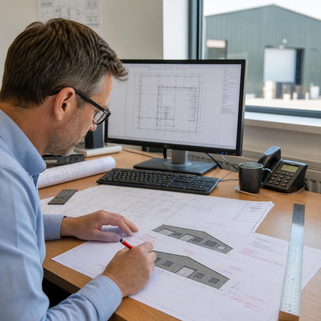
Where steel roofing or cladding will be prominent from a road, public viewpoint or neighbouring property, the planning authority may also ask for contextual drawings or visualisations. These can show the proposed building in relation to nearby rooflines, boundaries, trees and other buildings, helping the case officer judge its appearance at site level rather than in isolation.
This is more likely to matter where the proposal introduces a noticeably different profile, colour, reflective finish or building height. A streetscene elevation, verified view or simple annotated context image may be appropriate, depending on the authority’s validation requirements. It should support the measured planning drawings rather than replace them.
Discuss your steel roofing and cladding planning drawings
Discuss your proposed steel roofing or cladding work with Buildings UK Ltd to establish the information needed for a suitable planning drawing package. Sharing site details, existing dimensions and intended materials will help define the next design stage.