
How are large openings accommodated in portal frame buildings?
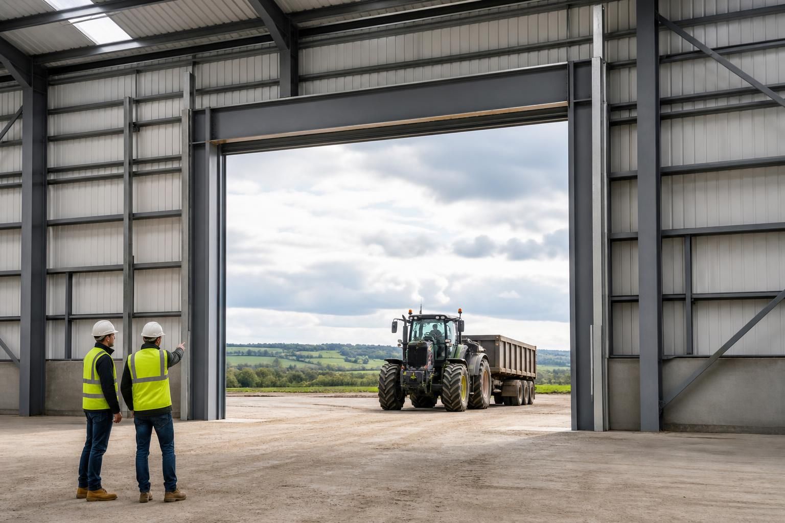
Large openings in portal frame buildings are accommodated by designing the surrounding steelwork to transfer roof and wind loads around the opening. Typically, reinforced jambs and a substantial head beam or goalpost frame support the structure, with the opening’s size, position and use considered during the bespoke structural design.
Large openings are treated as deliberate interruptions to the portal frame rather than as ordinary gaps in the cladding. Their design must preserve the building’s strength, stability, clear internal dimensions and weather resistance while allowing doors, shutters or access routes to operate as intended.
The position of the opening is the first major consideration. An opening in a side elevation can interrupt an eaves column and affect the way wind forces are carried through the frame. An opening at a gable end may require a different arrangement because the gable framing, end-wall wind posts and roof bracing all influence the available support. Openings close to corners, eaves or portal haunches generally require particularly careful detailing because these areas already carry significant forces.
Several structural arrangements may be suitable, depending on the required clear width and height:
- Reinforced side supports: jambs at each side of the opening can be designed as substantial columns or built-up members to carry vertical reactions and resist bending.
- Transfer members: a head beam, lintel or deeper steel member can collect loads that would otherwise pass through the interrupted part of the frame and direct them into the jambs.
- Additional portal action: where the opening is wide or positioned within a critical bay, the surrounding steelwork may be arranged to act as a secondary rigid frame.
- Local strengthening: plates, heavier sections, haunch modifications or additional cleats may be used at connections where forces become concentrated.
The required clear opening is not the same as the overall structural opening. The design must allow for the thickness of jamb members, door frames, guides, tracks, seals, flashings and any tolerances needed for installation. For vehicle access, the stated width and height should reflect the largest vehicle or equipment that must pass through, including allowances for manoeuvring and future changes in use. A door that fits the framed aperture may still provide insufficient practical clearance once its operating gear and weather seals are installed.
Door type also affects the surrounding steelwork. Sliding doors impose loads through their tracks and may need separate support at the head or alongside the opening. Roller shutters and sectional doors can add concentrated reactions and may require a suitably stiff head member to prevent excessive movement. Bi-folding or hinged doors can introduce local forces at pivots, hinges and holding points. These operational loads should be included in the structural design rather than left to the cladding or door installer.
Wind loading is another important factor. A large open doorway can change the pressure acting on the building, particularly when doors are open or when openings occur on more than one elevation. The frame, end walls, bracing and connections must be assessed for the relevant external and internal pressure conditions. Bracing should not be positioned where it blocks the opening, and its layout may need to be adjusted so that stability is maintained without restricting access.
The roof and wall cladding must be coordinated with the steelwork. Cladding rails, side rails and flashings may need to stop, be trimmed or be supported around the aperture. Door heads and jambs should provide suitable fixing lines, while movement joints and drainage details help prevent water entering at the opening. If the building has insulation or controlled internal conditions, the door perimeter also needs an appropriate sealing and condensation-control detail.
Large openings can influence the spacing of adjacent portal frames. A standard bay arrangement may be retained where the opening fits within a suitable bay, but a wider access route may require altered frame spacing, an intermediate support or a specially designed end frame. These choices affect fabrication, transport, erection sequencing and the position of internal columns, so they should be settled before the steel is detailed.
For a bespoke portal frame, the design information should identify the opening’s exact location, clear dimensions, door weight and type, operating method, likely impact or vehicle loads, required headroom, and any future expansion plans. The structural calculations can then establish member sizes, connection requirements, deflection limits and the need for local reinforcement. Planning elevation drawings show the external arrangement, while fabrication information defines the steel members and connections needed to construct it accurately.
Where an opening is expected to be enlarged later, the surrounding frame should be designed with that possibility considered from the outset. Retrofitting a wider opening may require temporary works, removal of cladding, replacement of members or strengthening of existing connections; it should not be assumed that an existing portal bay can simply be cut back without a new structural assessment.
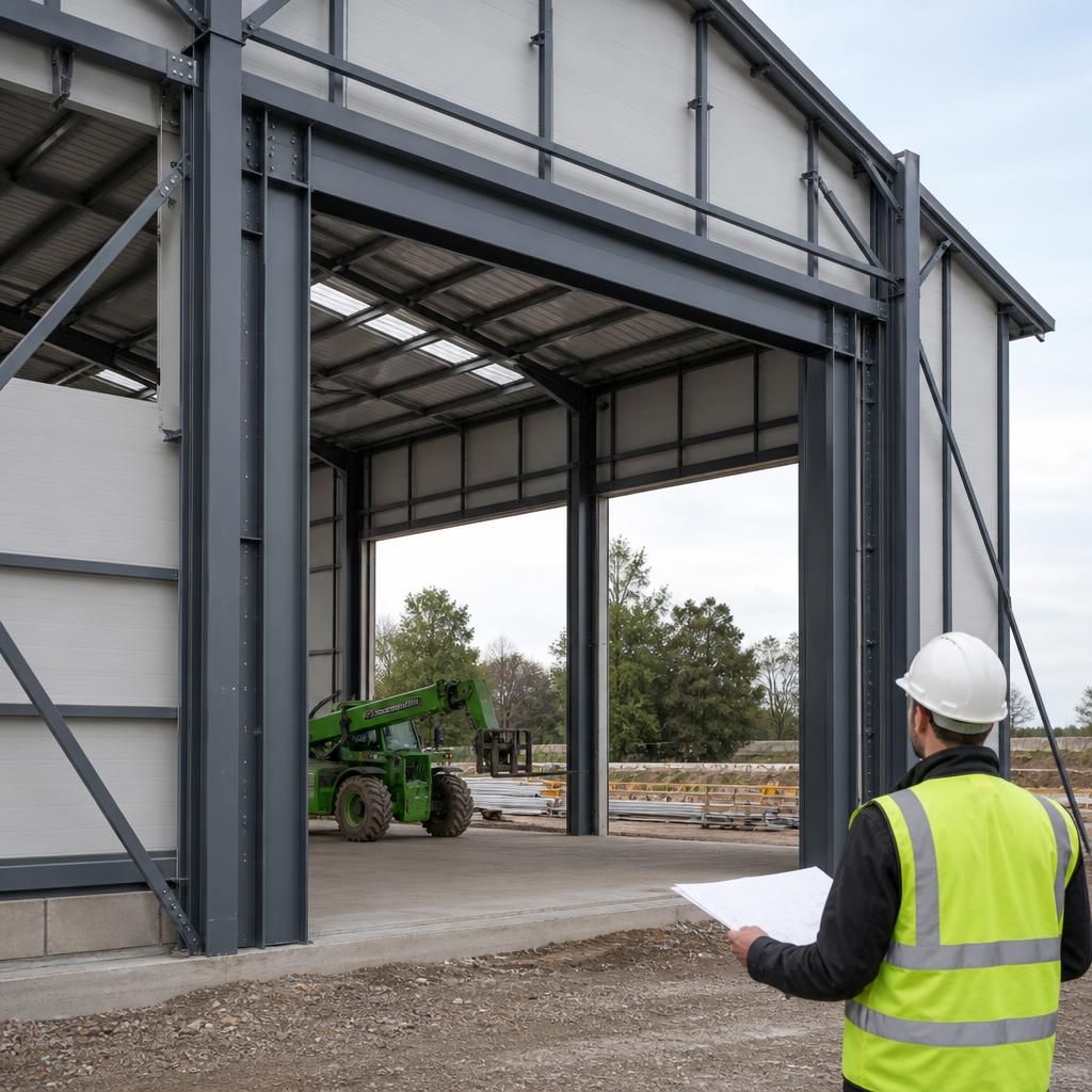
Large openings can affect stability during erection as well as in the completed building. Until the surrounding columns, head member, connections and bracing are fully installed, the aperture may leave parts of the frame less restrained than they will be after cladding and doors are fitted. The erection sequence should therefore identify any temporary supports or bracing required and ensure that the opening steelwork is connected before loads are introduced.
This is particularly important where the opening occupies a substantial part of a bay or is close to a gable or corner. The completed design should distinguish between permanent structural members and temporary erection aids, so the finished building does not rely on supports that are removed during construction.