
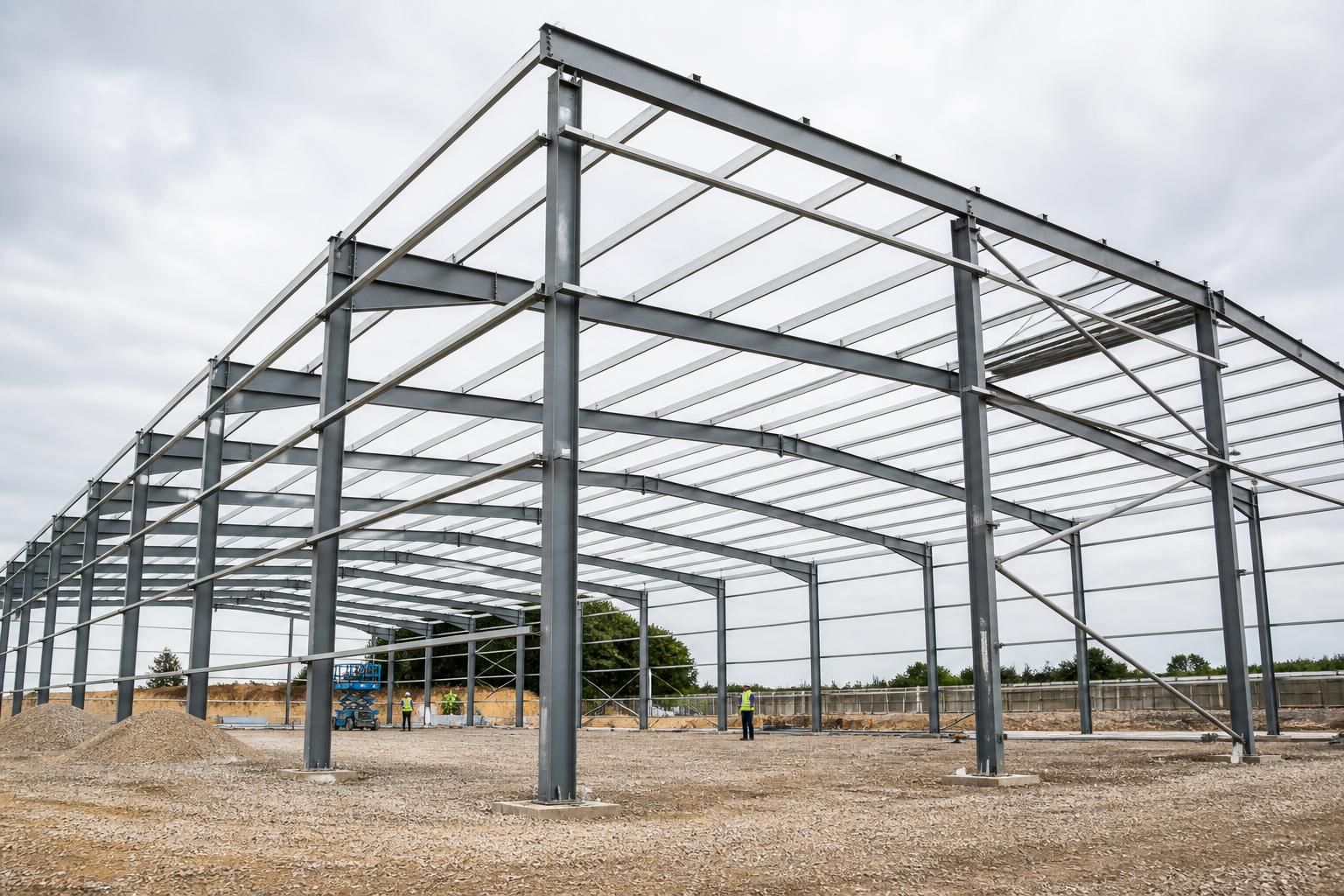
Which loading conditions should a portal frame building be designed for?
A portal frame building should be designed for permanent (dead) loads, imposed loads from use and maintenance, wind loads, and snow loads, together with any relevant accidental or site-specific actions. The structural design should assess how these loads combine across the frame, including effects on the foundations, connections, cladding and bracing.
A portal frame building should be designed against the complete set of actions that may affect it during construction, use and maintenance, not simply the weight of its steelwork. The design basis should identify the intended use, site exposure, building arrangement, supported equipment and likely future alterations, then assess each action individually and in the combinations required by the relevant structural design standards.
Permanent actions include the self-weight of the rafters, columns, haunches, purlins, side rails, bracing and connection components. The calculation should also include the weight of roof and wall cladding, insulation, liner systems, gutters, services, suspended ceilings and any permanently fixed equipment. Items such as solar panels, ventilation plant or internal handling systems need to be included when they form part of the planned installation. Their weight must be transferred through the secondary steelwork and portal frame without creating unaccounted-for point loads.
Use and maintenance actions depend on how the building will operate. Roof areas may require an allowance for people carrying out inspection or maintenance, while internal floors, mezzanines, storage platforms and suspended items can introduce separate imposed actions. Agricultural buildings may need provision for fixed handling or feeding equipment; industrial buildings may contain conveyors, plant or storage systems. These actions should be defined before fabrication because a frame intended for general storage may not be suitable for concentrated loads from machinery or a mezzanine.
Wind assessment is particularly important for portal frames because wind can produce both horizontal loading and roof uplift. The design considers the building location, terrain, height, topography and exposure, together with the geometry of the roof and elevations. External pressure varies across the roof and walls, with edge and corner zones often attracting different pressures from the central areas. Internal pressure must also be considered, especially where large doors, loading bays or other openings can change the pressure within the building.
Wind should be checked from the directions that produce the most demanding effects in the transverse and longitudinal stability systems. A building may experience compression in one member and uplift or reversal of force in another when the wind direction changes. The checks therefore extend beyond the main rafters to purlins, side rails, eaves connections, bracing, cladding fixings, column bases and foundations. Door positions and the operational condition of large openings should be included in the design assumptions.
Snow actions are determined from the site and the form of the building. Roof pitch, roof shape, parapets, adjacent structures and local obstructions can affect how snow accumulates. An even layer is not always the critical arrangement: drifting can create an unbalanced load, placing greater demand on one side of a portal or on local areas of the roof. The design should also consider whether future extensions or neighbouring buildings could alter the way snow collects at the roof edge.
Snow loading is not limited to the primary frame. Purlins, sheeting rails, roof coverings, gutters and their fixings must carry the resulting actions and transfer them safely to the columns and foundations. Roof drainage should be coordinated with the structural design, since water accumulation caused by restricted drainage can create an additional ponding risk that is separate from the assumed snow condition.
Site-specific actions may govern the design where the building includes features beyond a simple enclosed shell. Examples include:
- overhead cranes, monorails, hoists or suspended handling equipment, including their vertical, horizontal, braking and impact effects;
- plant, conveyors, fans and machinery that impose concentrated, cyclic or vibration-related actions;
- large roller doors, loading equipment and vehicle movements near the frame;
- internal storage, racking, mezzanines or suspended services;
- solar panels, roof-mounted plant and future service installations;
- thermal movement in long buildings or where sections of the structure are exposed to different temperatures;
- accidental actions such as vehicle impact, local damage or other hazards identified by the building’s use and risk assessment.
Fire resistance is addressed through the required fire strategy and may affect member protection, section selection and connection detailing. Where the building stores combustible materials or contains processes with a particular hazard, the structural engineer should receive that information at the design stage rather than treating it as a later operational issue.
The critical calculation is usually not an isolated load but a combination of actions. Design checks distinguish between ultimate limit states, which assess strength and stability, and serviceability limit states, which assess deflection, movement, vibration and suitability in normal use. Wind, snow, imposed actions and equipment loads are combined according to the applicable design rules and the probability of them acting together. Different combinations can govern different components: uplift may control the foundations, lateral movement may control bracing, and deflection may control purlins or cladding even where member strength is adequate.
The load path should be followed from the roof and walls through the secondary steelwork, rafters, columns, base connections and foundations into the ground. This includes checking frame sway, rafter bending, column buckling, lateral restraint, connection capacity and foundation resistance to sliding, overturning and uplift. Ground conditions are therefore part of the loading assessment: a frame can be structurally adequate above ground but still require revised bases or foundation details if the soil cannot resist the calculated reactions.
The design information should record the assumptions used for building use, openings, cladding, equipment, roof access, site exposure and possible future additions. Changing a door arrangement, adding solar panels, installing a crane or attaching services after the frame has been designed can alter the load path and invalidate earlier assumptions. Buildings UK can develop bespoke design information including planning elevation drawings and isometric fabrication blueprints, but the loading criteria must be established accurately before those details are finalised.
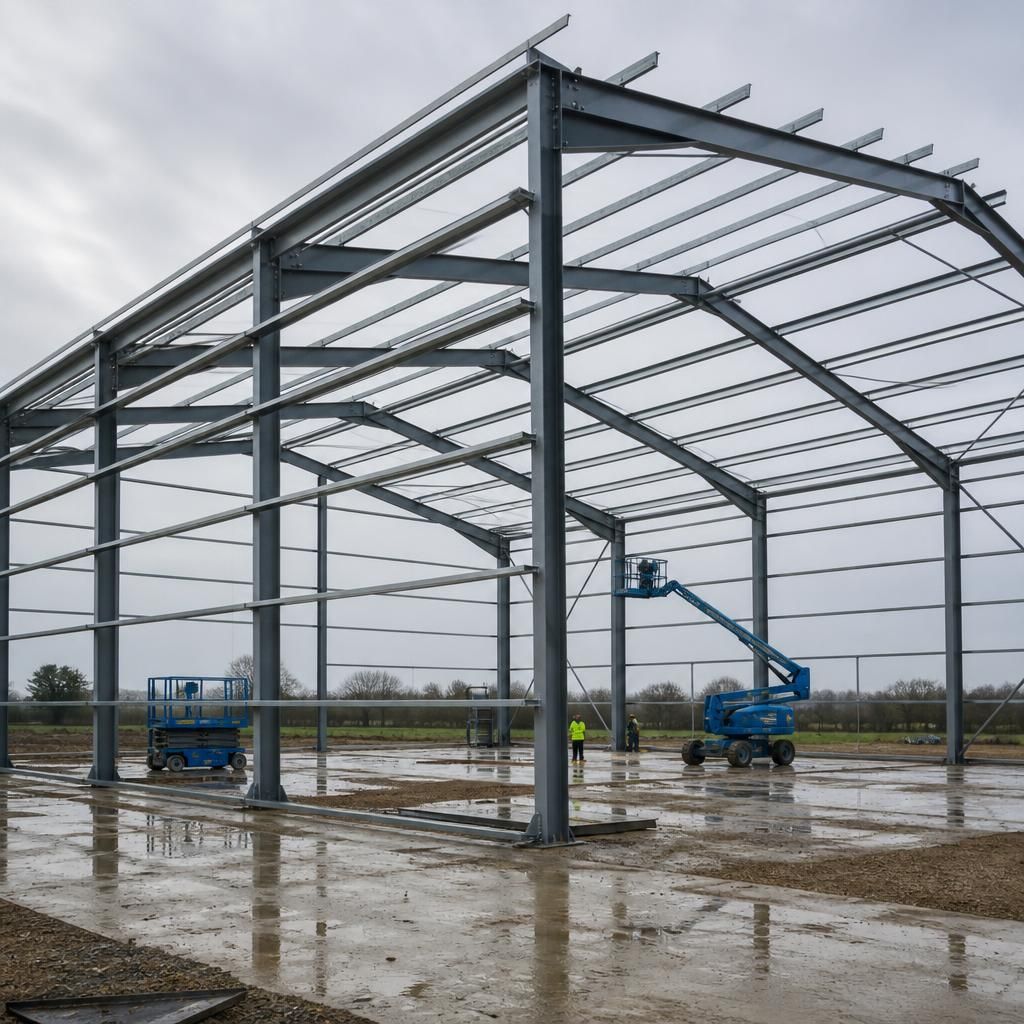
Construction-stage loading must be assessed separately from the conditions expected once the portal frame is complete. During erection, parts of the structure may be temporarily unsupported, bracing may not yet form its final stability system, and lifting operations can introduce forces that do not occur during normal use.
- Temporary instability while rafters, columns and bracing are being connected
- Loads from lifting equipment, access platforms and stored materials
- Wind acting on an incomplete frame or partially clad building
- Temporary restraints, props and erection bracing required by the construction sequence
The design and erection method should therefore be coordinated. A frame that is adequate in its completed configuration may need additional temporary measures until all permanent connections, bracing and cladding are in place.