
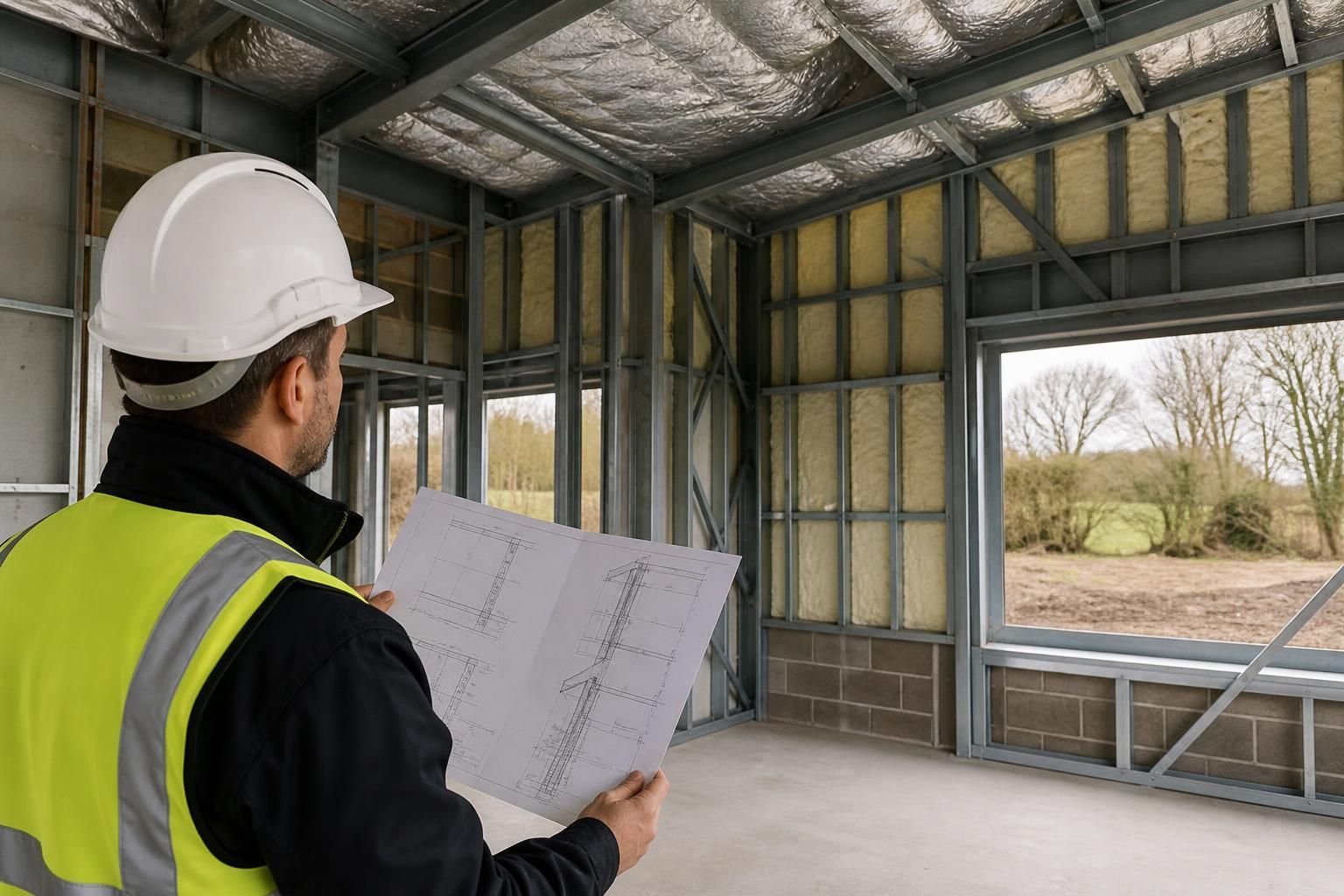
What thermal detailing does a steel frame house or extension require?
A steel frame house or extension requires continuous insulation, carefully designed junctions and thermal breaks to limit heat loss and prevent cold bridging through the steelwork. The detailing should coordinate the frame, wall, roof, floor, openings and connections so the completed construction meets the relevant UK building regulation requirements for insulation, condensation control and energy performance.
Thermal detailing is the design of the building’s layers and junctions so that heat flow, internal surface temperatures, air movement and moisture are controlled together. In a steel frame house or extension, this means specifying a complete wall, roof and floor build-up rather than choosing insulation in isolation. The design should be assessed against the relevant UK building regulations, including the energy-efficiency and condensation provisions applicable to the project’s location.
Wall build-up
A typical steel-framed wall needs a coordinated arrangement of external weather protection, sheathing, the structural frame, insulation, an airtight or vapour-control layer where required, and the internal lining. The position of each layer matters. Insulation fitted only between steel studs may leave the frame acting as a route for heat flow, so the design may need a continuous insulation layer on the warm or cold side of the frame, depending on the chosen construction method. The specification must also account for fixings, rails, brackets and other components that pass through the insulation.
The wall design should be checked for local cold spots at the base track, corners, intermediate floors, roof junctions and around structural openings. These areas can have a much greater influence on performance than an uninterrupted section of wall. Details should show how insulation returns into corners and how gaps are avoided when boards, quilt or blown materials meet the frame and sheathing.
Steelwork connections and thermal bridges
Steel columns, studs, portal elements, lintels and connection plates can create thermal bridges where they cross or interrupt the insulated envelope. The designer should identify these locations and use an appropriate combination of structural arrangement, separated components, insulating layers and thermal break materials. A thermal break must be compatible with the loads, moisture conditions, fire strategy and fixing method; it is not simply a piece of insulation inserted wherever steel meets another material.
Thermal-bridge assessment may be carried out using calculated junction values or a suitable approved calculation method. The resulting values can feed into the energy assessment and help establish whether the details produce excessive heat loss or low internal surface temperatures. Where a junction cannot be made fully continuous, the design should minimise the bridge and demonstrate that the remaining effect is acceptable.
Roof, eaves and wall-to-roof junctions
At the eaves, the roof insulation, wall insulation, airtight layer and roof or wall sheathing must meet without a discontinuity. The detail should preserve the required roof ventilation or vapour-control arrangement while avoiding a narrow uninsulated strip beside the wall plate or top rail. Similar care is needed at verges, roof abutments, parapets, dormers and rooflights. Steel purlins, eaves members and support brackets should be included in the thermal-bridge review rather than treated as secondary items.
Where a warm roof is used, the insulation is generally arranged to keep the main structural zone within the intended thermal envelope. Where insulation is placed between or below structural members, the designer must check the effect of repeating steel bridges and provide enough continuity at junctions. The roof covering, underlay, ventilation and vapour-control layers must also be compatible with the condensation assessment.
Floor and foundation interfaces
The junction between the steel frame, floor slab, foundation and external wall is particularly important because the frame often begins close to the ground and the slab edge can bypass wall insulation. The detail should show the relationship between the perimeter insulation, damp-proof course, damp-proof membrane, wall insulation and base track. It should also prevent moisture from reaching materials that are not intended to remain damp.
For a suspended floor, the design should address the edge zone, supports and service penetrations. For a ground-bearing slab, it should address the slab perimeter and the connection between floor insulation and wall insulation. The finished floor level, thresholds and external ground levels must be coordinated so that thermal continuity does not compromise drainage or moisture protection.
Windows, doors and other openings
Openings require more than an insulated cavity around the frame. The window or door frame should be positioned in relation to the insulation line, with the surrounding insulation returned into the reveal where possible. The sill, jamb and head details need to control heat loss, air leakage and rainwater penetration while allowing the frame to be fixed securely to the structure.
Steel lintels, goalposts, trimmers and support angles around large openings can introduce additional thermal bridges. Their position and protection should be shown on the construction details. The same principle applies to rooflights, glazed links, entrance thresholds and any projecting steelwork that connects the interior to external elements.
Airtightness and moisture control
Thermal performance depends on both insulation and airtightness. The air-control layer should be identified clearly on the drawings and continued through wall-to-floor, wall-to-roof and opening junctions. Seams, laps, tapes, membranes, sealants and service penetrations need a specified treatment. A steel frame does not automatically provide an airtight enclosure, particularly where linings, sheathing boards or membranes are interrupted by connections and building services.
Vapour movement and interstitial condensation should be considered for the full build-up, including seasonal moisture conditions and the intended internal environment. A vapour-control layer may be needed, but its position and vapour resistance must suit the rest of the construction. Sealing a junction without checking drying potential can create a moisture risk. Internal surface temperatures should also be reviewed at steel connections, corners and reveals to reduce the likelihood of surface condensation and mould.
Services and penetrations
Electrical cables, plumbing, ventilation ducts and structural fixings should be planned before the insulation and air-control layers are finalised. Services that puncture the airtight layer need properly detailed collars, grommets or sealed sleeves. Where possible, a service zone can reduce the number of penetrations through the main air and vapour-control layer. Recessed fittings, extractor terminals and flues require particular coordination with the insulation, fire stopping and manufacturer’s installation requirements.
Extensions and connections to existing buildings
An extension introduces a junction between a new insulated envelope and an existing wall or roof, which may have a different construction and thermal performance. The detail should establish whether the existing insulation is retained, removed, continued or supplemented, and how the new airtight and moisture-control layers connect to it. The interface around the opening between the original building and extension should be assessed separately from the new external corners.
Changes in floor level, roof height and wall thickness can create awkward narrow areas where insulation cannot be installed continuously. These constraints should be resolved in the design rather than left to site improvisation. Movement, differential settlement, fire separation and rainwater management also need to be coordinated because a thermally efficient connection must still perform structurally and protect the building from weather.
Information needed for compliance
The thermal package should normally include annotated section details, the proposed material build-ups, insulation specifications, junction calculations where required, and a clear description of the air and vapour-control strategy. The energy assessment and building regulation submission should use the same construction information as the fabrication and installation drawings. Any change to steel size, bracket position, insulation thickness or cladding system should be reviewed for its effect on the thermal calculations.
- Confirm the applicable building regulation requirements and local approval process.
- Define the thermal line, airtight line and moisture-control strategy on the drawings.
- Check repeated steel bridges as well as major one-off connections.
- Detail the base, corners, openings, eaves, verges, roof junctions and service penetrations.
- Coordinate insulation, fire stopping, structural fixings, ventilation and weatherproofing.
- Record any site changes and obtain a design review before covering altered work.
The most reliable approach is to resolve these details at the design stage and carry the same information through structural calculations, fabrication drawings, construction details and site inspection. Building control approval remains separate from the designer’s technical coordination, and the completed work must match the assessed build-up if the intended thermal performance is to be achieved.
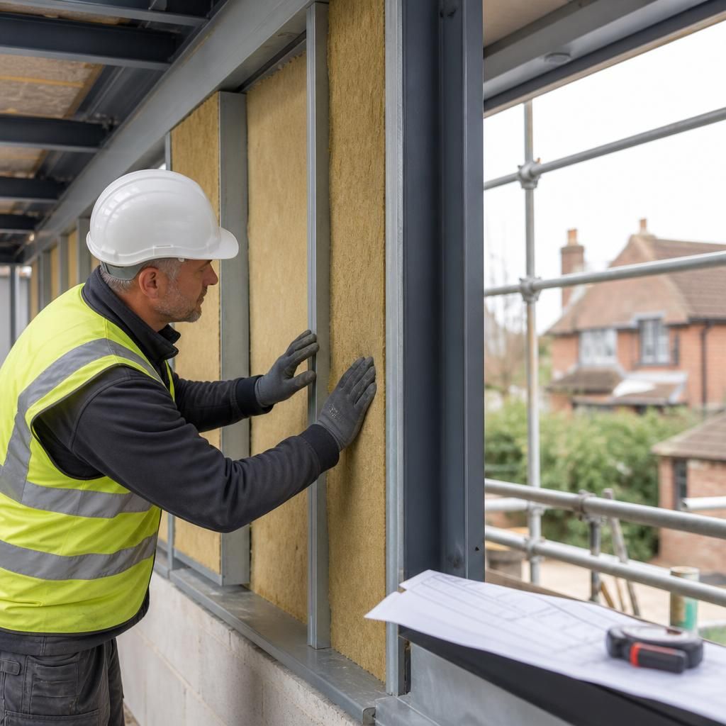
Thermal detailing must allow for installation tolerances, not just the ideal dimensions shown on a design drawing. Insulation boards should meet tightly at joints, flexible insulation should remain sufficiently full around framing, and membranes must not be pulled away from corners or crushed beneath rails and fixings. Small gaps at changes in material or level can create disproportionately cold areas once the enclosure is complete.
A useful section detail therefore identifies the order in which adjoining layers are installed and the space available for taping, sealing and fitting insulation. The wall, floor and roof details should be checked before they are covered, particularly where steelwork, brackets or service routes restrict access. This confirms that the intended thermal line has been built continuously rather than merely specified on paper.