
What does a steel framed extension design package include?
A steel framed extension design package includes planning elevation drawings and isometric fabrication blueprints tailored to the proposed structure. These documents set out the building’s appearance and provide the detailed information required to manufacture the steel frame accurately.
A steel framed extension design package brings together the drawings needed to define the proposed extension and manufacture its frame. For Buildings UK Ltd, the core package comprises planning elevation drawings and isometric fabrication blueprints, with the content tailored to the building’s intended form, dimensions and use.
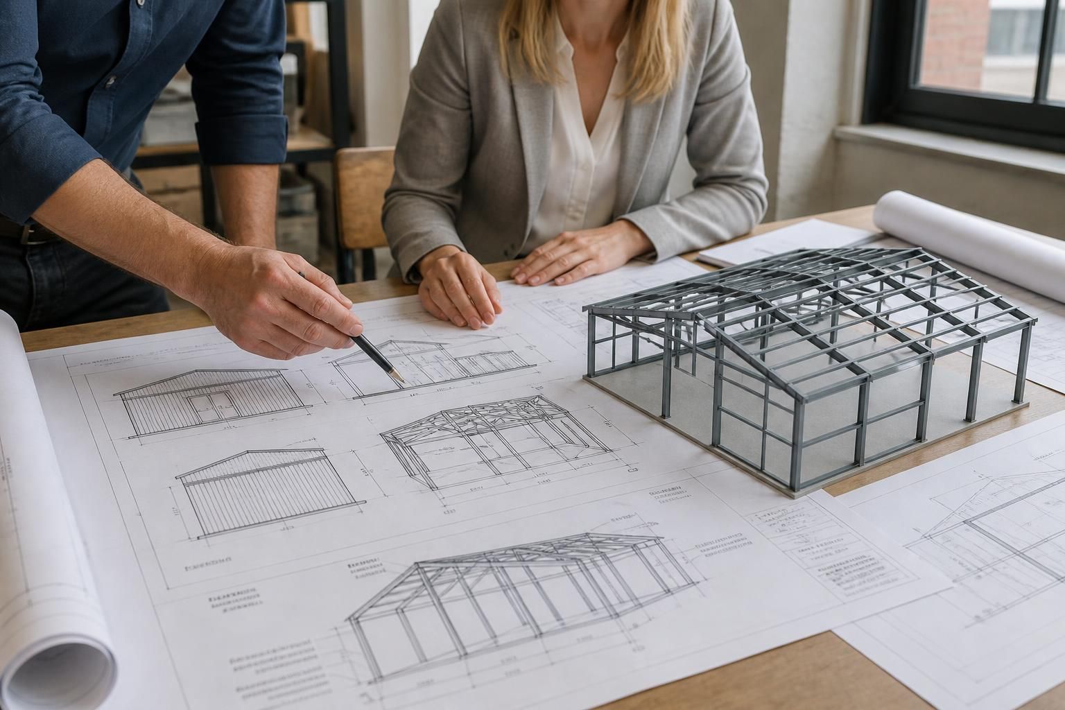
The planning elevation drawings communicate the extension’s external appearance. They can show the proposed roof profile, wall lines, openings and principal dimensions from each relevant elevation. This gives the project team a clear visual reference for assessing how the extension will look alongside the existing property and provides suitable information for planning discussions where required.
The isometric fabrication blueprints provide the steelwork information in a three-dimensional format. They set out the arrangement of the frame and show how its individual steel members relate to one another. Depending on the design, this information can include member positions, overall dimensions, connection locations and details needed to interpret the frame accurately during manufacture and erection.
Together, the two drawing types serve different purposes:
- Planning elevation drawings: describe the proposed external appearance and help communicate the design to planning professionals, building owners and other project participants.
- Isometric fabrication blueprints: describe the steel frame’s configuration and provide the detailed manufacturing information required to produce the bespoke structure.
The package is prepared around the specific extension rather than a standard kit. Its design therefore needs to reflect the proposed footprint, the relationship with the existing building, the required access and openings, and the way the new space will be used. These factors influence the arrangement of the steelwork and the information shown on the drawings.
It is important to distinguish design drawings from statutory approvals. Planning elevations may support a planning submission, but the drawings themselves do not automatically constitute planning permission. Similarly, whether separate structural calculations, Building Regulations information or other specialist documents are needed depends on the project and the requirements of the relevant professionals and authorities. These requirements should be established before construction begins.
For a client or architect reviewing a package, the key checks are whether the extension’s intended appearance is represented clearly, whether the steel frame is fully defined for manufacture, and whether the drawings align with the wider architectural and regulatory information for the project. Any changes to the brief, dimensions or openings should be resolved before the fabrication information is used to manufacture the frame.
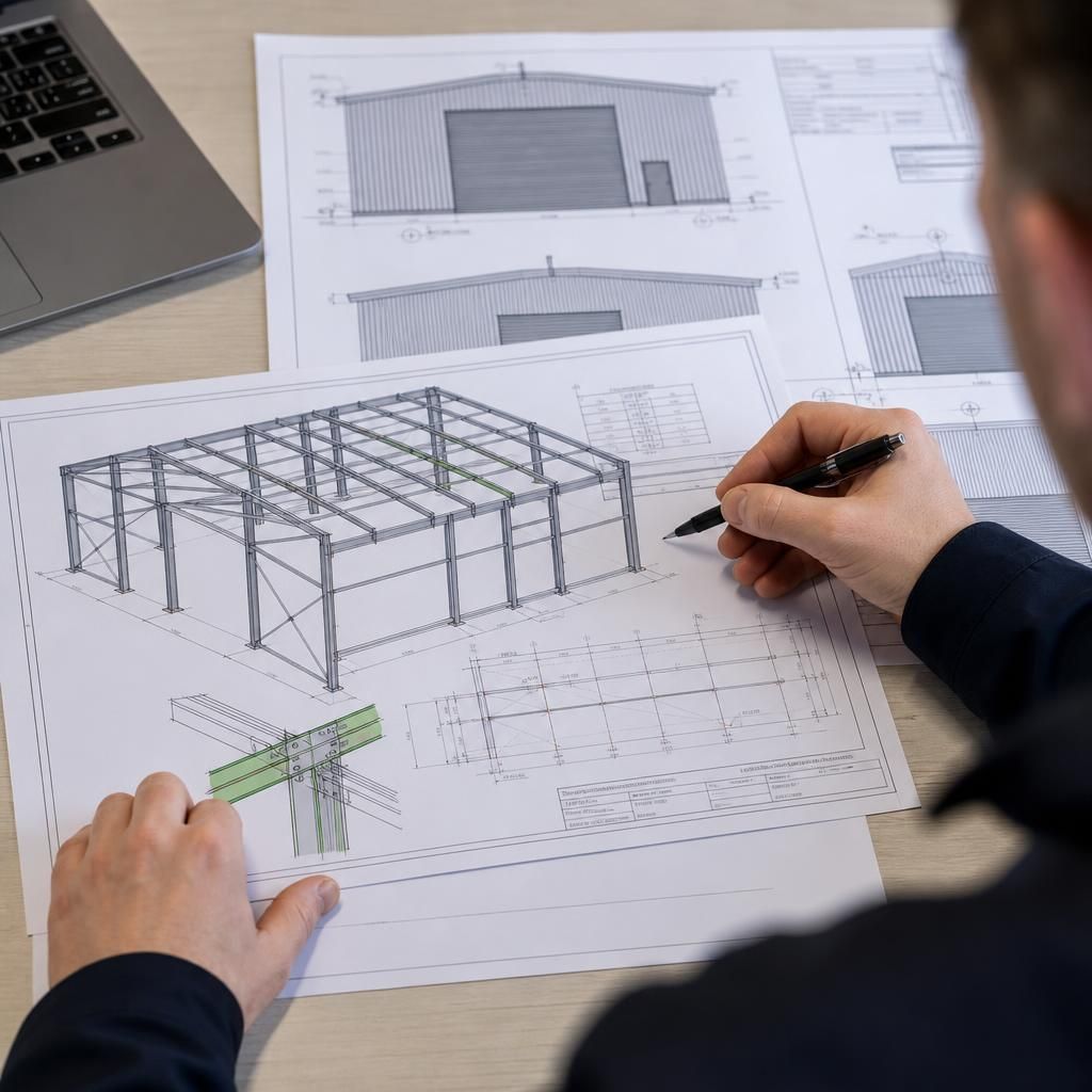
A useful design package should make each drawing easy to identify and use. Drawing titles, reference numbers, revision details, dimensions and relevant notes help the architect, client and fabricator confirm that they are working from the same information. This is particularly important when amendments are made during the design process.
Before the package is approved for manufacture, check that the latest revisions are clearly marked and that the drawings correspond with the agreed extension brief. This provides a clear record of the design information used to develop the steel frame.