
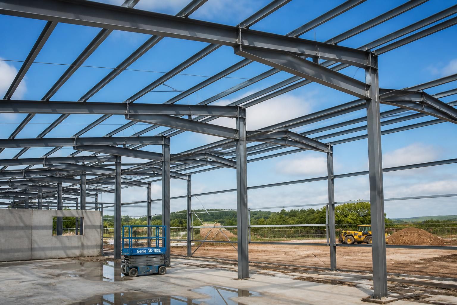
How are steel framing components selected for each building element?
Steel framing components are selected by assessing each building element’s structural role, span, loading, connections and environmental exposure. Columns, rafters, purlins, rails, bracing and connection details are then designed as a coordinated system to suit the building’s intended use and layout.
Steel framing components are selected by matching each element to the forces it must carry, the way those forces travel through the structure, and the practical requirements of the finished building. The resulting specification considers the complete frame rather than treating columns, roof members, wall members and connections as separate products.
Columns are sized according to the vertical loads from the roof and any supported floors, together with the horizontal forces transferred through the frame. Their height, spacing and restraint conditions affect their resistance to buckling. Column bases also need to suit the foundation arrangement and the forces at ground level, while their position must allow for vehicle access, machinery, livestock movement, storage layouts or other operational requirements.
Rafters and other primary roof members are selected for the roof span, pitch, imposed loads and the spacing of the supporting columns. The design also allows for the weight of roof coverings, insulation, services and equipment where these form part of the building brief. Deflection is considered as well as strength, because excessive movement can affect cladding, drainage, doors, partitions and internal finishes.
Purlins and side rails support the building envelope and transfer loads back to the primary frame. Their spacing is coordinated with the chosen cladding system, its fixing requirements and the anticipated wind actions on the roof and walls. Around large doors, personnel doors, windows, ventilation openings and translucent panels, the arrangement may need additional framing so that the opening does not interrupt the intended load path.
Bracing components provide stability along and across the building. Their location is selected in relation to the building’s length, access points, openings and internal layout. Where a conventional diagonal brace would obstruct a doorway, loading route or usable floor area, the stability arrangement must be reviewed as part of the overall frame design rather than added as an afterthought.
Connections are selected to transfer the calculated forces between members while allowing the frame to be fabricated, transported and assembled correctly. Designers consider bolt groups, end plates, cleats, gussets, welds and the tolerances needed at each junction. A connection can be structurally adequate yet unsuitable if it prevents cladding from being fixed, conflicts with another component or makes erection unnecessarily difficult, so detailing is coordinated with the whole building package.
The building’s use influences the selection of every element. An agricultural building may require clear access for machinery, robust wall arrangements and space for ventilation or handling systems. An equestrian building may place greater emphasis on unobstructed internal areas, safe internal finishes and openings suited to stable or riding layouts. An industrial building may need to accommodate storage, process equipment, cranes, services or floor loads. These requirements are translated into design loads, dimensions and connection details rather than dealt with through a standard frame size.
Selection also takes account of the site and the proposed envelope. Building dimensions, roof form, location of openings and exposure affect the actions applied to the frame, while the cladding specification determines where secondary members are required. The design package can then show the relationship between the individual components through planning elevation drawings and isometric fabrication blueprints.
For a bespoke steel frame, the final choice is therefore a coordinated set of member sizes, spacings, restraints and connections. Buildings UK develops British-made, CE-marked hot rolled steel framed building solutions around the intended layout and use, with the component information prepared for manufacture as part of the wider structural design.
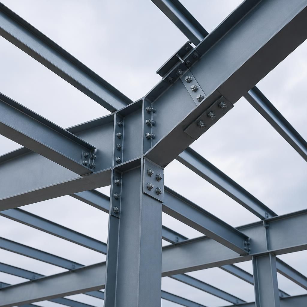
Steel framing components are not always selected as one repeated arrangement across the whole building. The requirements can change between typical bays, corners, eaves, ridges and areas containing doors, windows, plant or lifting equipment. These zones may need different member sizes, closer spacing, local strengthening or altered connection details to deal with the forces and restraints present there.
This zonal approach helps keep the frame proportionate to its actual requirements. Areas carrying ordinary envelope loads can follow the standard arrangement, while local details are developed where the structure is interrupted or subjected to additional forces. The distinction is recorded in the fabrication information so that variations between building elements are clear during manufacture and assembly.
Discuss your steel framing component requirements
Discuss your proposed building layout and intended use with Buildings UK to identify the steel framing components required for each element. The team can develop a bespoke design package for your project, including planning elevation drawings and isometric fabrication blueprints.