
What steel sections are used in a steel frame building?
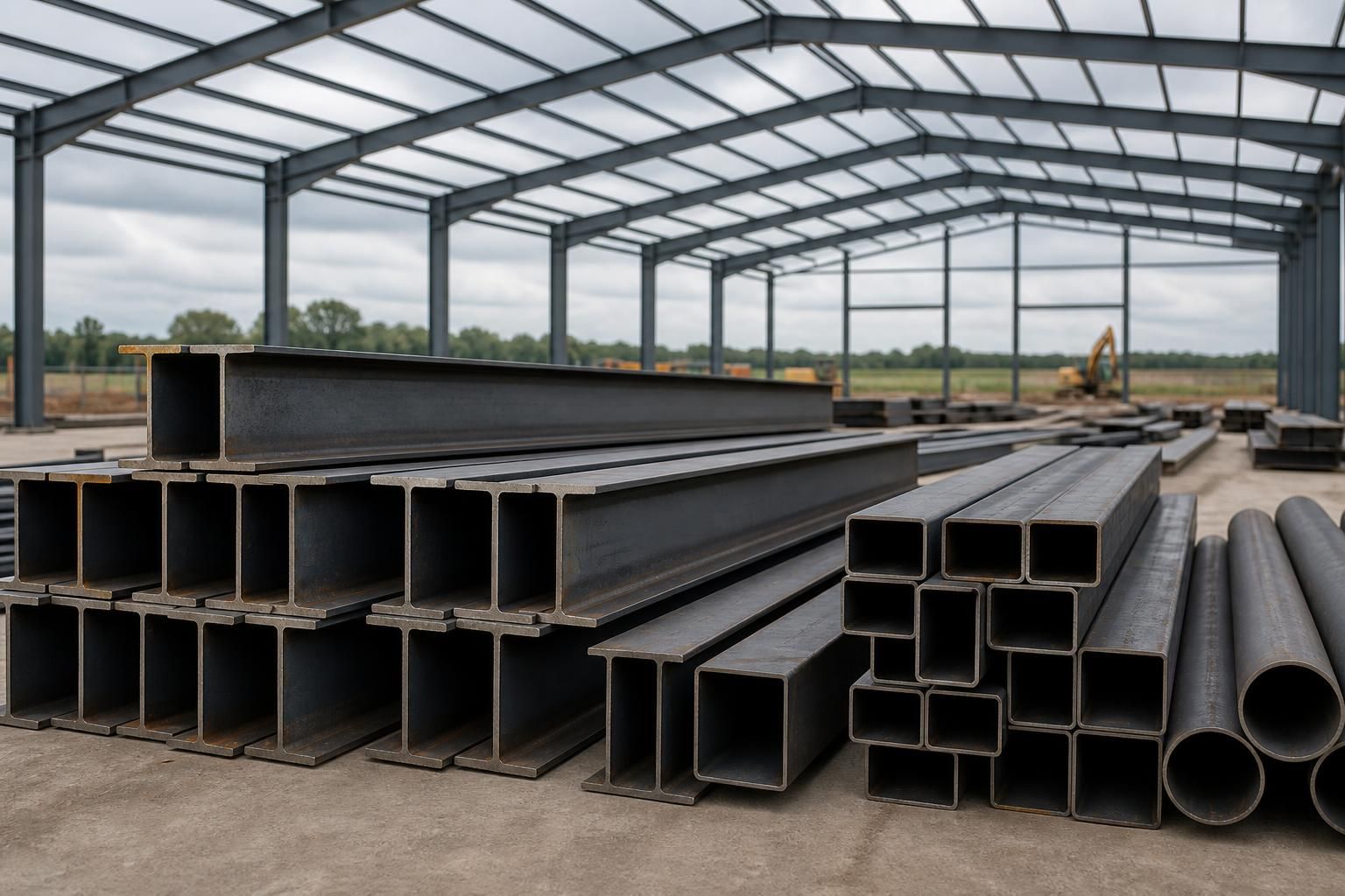
A steel frame building typically uses hot-rolled I-sections for primary columns and rafters, with channels, angles, hollow sections and plates used where the design requires additional support or connection details. Cold-formed Z or C sections are commonly used for secondary steelwork such as purlins and side rails, transferring roof and wall loads to the main frame.
The steel sections specified for a frame building depend on the loads, spans, building use, connection arrangement and required degree of stability. A typical design combines several section types rather than using one profile throughout, with each selected for its strength, stiffness, weight, ease of fabrication and resistance to buckling.
Universal beams and columns: These are rolled I-shaped sections commonly used where members must carry substantial bending or compression forces. Their wide flanges provide resistance to bending about the major axis, while the web transfers shear and separates the flanges. The designer may use different beam or column sizes within the same building because roof spans, imposed loads, bay widths and support conditions are not always identical.
Universal columns have a stockier proportion than many beams and are suited to carrying vertical loads. They can be used as standalone columns or combined with beams through bolted or welded connections. The choice between a beam and a column section is based on the forces and slenderness of the member, not simply whether it is vertical or horizontal.
Channels: Channel sections have a web and two flanges on one side of the web. They are useful for edge members, framing around openings, cleats, trims and other details where an open section is easier to connect or position. A pair of channels can also be arranged together when the design requires greater capacity or a particular connection configuration.
Angles: Equal and unequal angles are L-shaped sections used for bracing, cleats, restraint members, framing details and secondary support. An angle is particularly useful where two surfaces need to be connected at right angles. Its capacity depends strongly on how it is connected, because an eccentrically loaded angle can experience twisting as well as direct tension or compression.
Hollow sections: Rectangular, square and circular hollow sections enclose the steel on all sides. This gives them useful resistance to torsion and provides a clean profile for columns, braces, posts, rails and architectural features. Rectangular hollow sections can be advantageous where members need different stiffness in two directions, while circular sections are often selected where loads and connections suit a symmetrical profile.
Hollow sections require careful connection detailing. Access for bolts, welds, inspection and protective treatment can be more restricted than with an open section. End plates, brackets, gussets or locally reinforced areas may therefore be needed to transfer forces safely into the member.
Plates and flat bars: Steel plate is used to make base plates, end plates, splice plates, gussets, stiffeners and connection components. These parts distribute loads, join separate members and prevent local distortion around bolts or welds. A plate may also be welded to a beam or column where the standard rolled profile does not provide sufficient bearing area or connection strength.
Tapered and built-up sections: Where a standard rolled section is not the most efficient option, a member may be fabricated from steel plates or formed with a changing depth. Tapered rafters can place more material where bending moments are higher and less where forces are lower. Built-up members are also used where the required span, load or clearance exceeds the practical range of a standard section, subject to detailed structural design and fabrication checks.
Secondary framing profiles: Z and C sections are widely used for purlins, side rails and other light secondary members. They support cladding and transfer its loads to the main frame. Their design must account for restraint provided by the sheeting, lap arrangements, local buckling and the forces introduced at supports. They are not interchangeable simply because they have similar dimensions; the orientation, continuity and connection method affect their performance.
How the sections are selected: The structural engineer considers permanent loads, imposed loads, wind actions, snow where relevant, equipment loads, serviceability limits and the way the building will be used. The analysis then establishes bending moments, shear forces, axial forces and deflections. Section properties, unrestrained lengths, buckling modes and connection capacity are checked against the applicable design requirements.
Practical factors also influence the specification. The section must be available in a suitable grade and length, fit within the building’s clearances, accommodate the proposed cladding and services, and allow fabrication, transport and erection. Open sections may simplify some bolted connections, while hollow sections can require more specialised end detailing. The final arrangement is therefore a balance between structural performance and buildability.
Protection and durability: The selected section must also suit the building’s exposure and maintenance requirements. Surface preparation and protective coatings are specified according to the environment, while fire protection may be required where the design or building use calls for it. Hollow sections, enclosed details and areas around connections need particular attention so that protective treatment is continuous and water cannot be trapped.
The steel schedule and fabrication drawings identify each member by its section, grade, length, orientation and connection details. Reviewing these documents alongside the design calculations helps confirm that the specified profiles match the intended loads, openings, bracing arrangement and cladding system. For that reason, section selection should be completed as part of the engineered frame design rather than chosen from appearance or isolated span information.
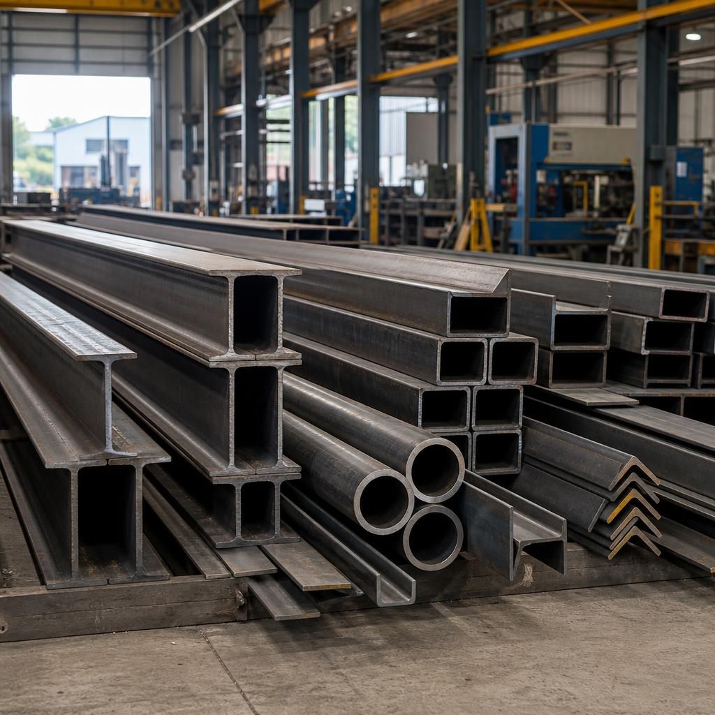
Steel sections are often identified on structural drawings by standard abbreviations as well as their full descriptions. UB and UC refer to universal beams and columns, while PFC identifies a parallel flange channel. RHS, SHS and CHS describe rectangular, square and circular hollow sections; EA and UA are commonly used for equal and unequal angles. Z and C designations usually indicate cold-formed secondary profiles.
The abbreviation alone does not define the complete member. The drawing or steel schedule should also state the section size, steel grade, length and any required treatment. Two members with the same general profile may have different capacities because their dimensions, material grade, restraint conditions or connection details differ. This information is therefore essential when checking that the sections shown on fabrication drawings correspond with the engineered design.