
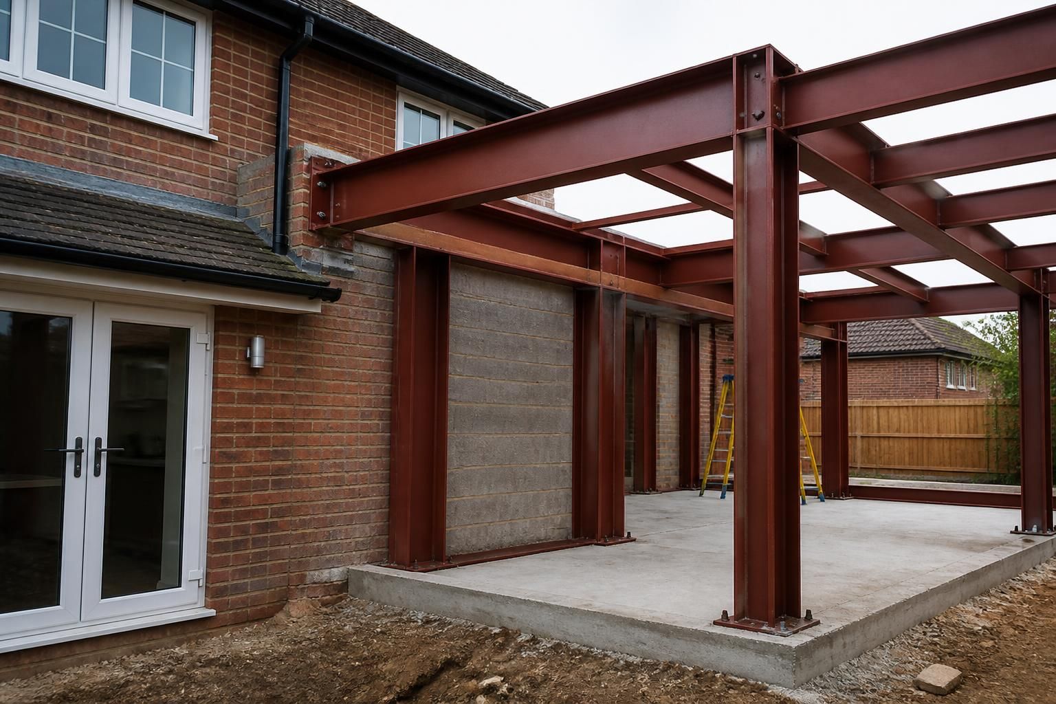
How is a steel frame house extension connected to an existing house?
A steel frame house extension is connected through engineered fixings to suitable parts of the existing structure, such as reinforced masonry, existing steelwork or new foundation supports, with the exact arrangement determined by the structural design. The junction is then detailed to manage movement, maintain stability and provide continuous weatherproofing between the extension and the original house.
A steel frame house extension is connected to the existing house by a designed interface between the new frame, the original building and the foundations. The connection must transfer vertical and horizontal loads safely while allowing for differences in movement, protecting the junction from water ingress and maintaining the performance of the external wall and roof.
The connection is designed around the existing structure. The type of wall, its condition, the position of foundations, the proposed openings and the loads from the extension all affect the detail. A structural engineer may connect the extension to suitable existing masonry, timber or steelwork, or design the new frame to stand largely independently with controlled restraint back to the house.
Typical structural connection points include:
- Steel beams or posts connected to existing structural walls where those walls can safely accept the additional loads.
- Bolted connection plates, brackets or restraint fixings between the new steelwork and verified parts of the existing structure.
- Base plates fixed to new concrete foundations, ground beams or other designed supports beneath the extension.
- Steelwork around a new or enlarged opening, such as the opening between the original house and the extension.
- Discrete wall ties or lateral restraints that stabilise the extension without relying on unsuitable finishes, outer leaves or non-structural partitions.
Anchors may be mechanical or resin-fixed, but their suitability depends on the masonry type, edge distances, embedment, spacing and the forces being transferred. Fixings should not be selected simply because they fit the steelwork. The supporting material must be checked first, particularly where the existing wall contains cavities, weak mortar, concealed services or signs of movement.
Where an opening is formed in the existing house, the surrounding wall may need temporary support before any masonry is removed. The permanent steel frame or lintel arrangement then carries the loads around the opening and transfers them to designed bearings or supports. The bearing length, padstones, local strengthening and connection between the steel members are determined by the calculations rather than by the appearance of the finished opening.
Not every extension should be rigidly tied to the house. If the existing and new foundations are likely to settle or move differently, the design may use a movement joint or a predominantly independent frame. In that arrangement, the extension remains stable on its own supports while the junction is detailed to prevent uncontrolled loads being imposed on the original building. Flexible seals, cover trims and movement-tolerant finishes may be used where appropriate.
The structural junction must also be weatherproof. The connection between the extension roof and the existing wall commonly requires carefully arranged flashings, cavity trays, membranes and drainage paths. At low-level junctions, damp-proof courses and cavity barriers must align with the existing construction so that moisture cannot bridge into the house. Roof coverings, wall cladding and window or door frames must be integrated with these layers rather than installed over an unplanned steel connection.
Thermal and fire performance are considered at the same interface. Steelwork passing through an insulated wall can create a thermal bridge unless the surrounding insulation and internal lining are designed around it. Where the extension adjoins a habitable part of the house, gaps and concealed cavities may also require fire stopping. The detail must preserve the required compartmentation and prevent smoke or fire from travelling through the junction.
A typical design and installation sequence is:
- Survey the existing house, including wall construction, visible cracking, floor levels, roof geometry and accessible foundations.
- Confirm the proposed layout, openings and load paths, then calculate the new steelwork, foundations, fixings and any temporary support.
- Expose or verify critical connection locations before manufacture where the available information is uncertain.
- Install the foundations and steel frame, keeping the work temporarily stable until the permanent bracing and restraints are complete.
- Form openings or remove sections of the existing wall only when the required temporary and permanent support arrangements are in place.
- Complete the structural fixings, movement details, insulation, fire stopping, membranes, flashings and internal or external finishes.
- Inspect the junction before it is enclosed, because fixings, bearings and weatherproofing layers become difficult to verify once covered.
Fabrication drawings should show the connection positions, member sizes, plates, bolts, welds, bearings and site tolerances. The accompanying construction details should show how the steelwork meets the wall, roof, floor and external envelope. This coordination is important because a structurally adequate connection can still cause problems if it obstructs drainage, interrupts insulation or leaves no practical route for installing the required fixings.
For a bespoke steel frame extension, Buildings UK Ltd can incorporate the connection requirements into the design package, including planning elevation drawings and isometric fabrication blueprints. The final arrangement should be based on the property-specific structural assessment and checked by the appropriate design professional before construction.

A steel frame connection and the surrounding building junction perform different jobs. A bracket, bolt or restraint transfers structural forces between the new frame and the existing building, while flashings, membranes, insulation and sealants protect the junction from water ingress, heat loss and concealed air movement. One element should not be assumed to replace another.
Design drawings should therefore distinguish the structural fixing from the envelope details around it. They should show where the load is transferred, which part of the existing construction receives the fixing, and how the wall, roof and internal finishes continue around the connection. This separation makes it easier to inspect the work and prevents a visually neat junction from concealing an incomplete structural or weatherproofing detail.
Plan your steel frame house extension connection
Discuss your proposed extension and existing house with Buildings UK Ltd to establish the information needed for a bespoke connection design. The design package can then set out the coordinated structural and envelope details for review before construction.