
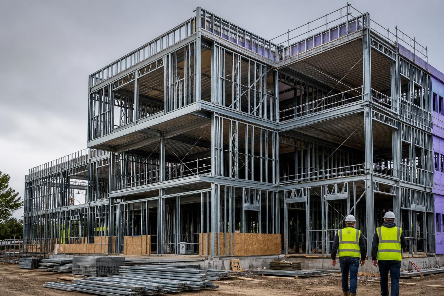
Can light gauge steel framing support multi-storey construction?
Yes, light gauge steel framing can support multi-storey construction when it is engineered for the building’s loads, stability and connection requirements. Its suitability depends on factors including storey height, floor spans, wind and imposed loads, fire and acoustic performance, and how the frame integrates with foundations and other structural elements.
Light gauge steel framing can be used for multi-storey buildings because its cold-formed steel members create a continuous structural system from the upper floors down to the foundations. The frame must be designed as a complete assembly rather than as a collection of individual wall studs, with the design accounting for vertical load transfer, lateral stability, floor construction, connections, fire resistance and the behaviour of the building as a whole.
How the load path is arranged
In a multi-storey light gauge steel frame, loads from the roof and floors are transferred through joists, floor members, load-bearing wall panels and their connections. Studs in the walls carry compression, while tracks and other framing components distribute loads and provide continuity between members. At each floor, the design must show how concentrated reactions are supported and how loads pass through openings, changes in wall layout and areas where upper-storey walls do not align directly with those below.
This alignment is important because light gauge members are efficient when loads remain controlled and reasonably uniform. Where an upper floor creates a point load, transfer arrangement or substantially different structural layout, additional framing may be required. The supporting structure beneath it may also need heavier sections or a separate steelwork solution, depending on the forces involved.
Floor systems and spans
Floor joists in a multi-storey building must resist both permanent loads, such as finishes and partitions, and imposed loads from occupants, furniture, storage or equipment. They also need to meet serviceability requirements. Excessive deflection, vibration or movement can affect finishes and the performance of partitions even when the members remain structurally safe.
Designers therefore assess joist spacing, span, bearing conditions, openings for services and the interaction between the floor and the supporting walls. Floor construction can also contribute to the building’s stability by acting as a diaphragm, transferring horizontal forces to braced walls or other stabilising elements. The floor-to-wall connection must be detailed to transfer these forces reliably.
Stability under horizontal forces
Multi-storey frames are affected by wind and other lateral actions as well as gravity loads. A light gauge steel design may use braced wall panels, sheathing, rigidly detailed connections or a combination of these methods to resist racking. The selected approach depends on the building’s geometry, openings, floor arrangement and the stiffness of the materials fixed to the frame.
Stability must be considered in both directions of the plan and over the full height of the building. Irregular layouts, large areas of glazing, offset walls and open ground-floor arrangements can make the load path less direct. The design should also consider temporary stability during construction, before all floors, sheathing and permanent bracing are complete.
Connections and member behaviour
Connections are central to the performance of a multi-storey light gauge steel frame. Thin-walled sections can be strong relative to their weight, but their design is affected by local buckling, distortional buckling, bearing, screw spacing and the possibility of eccentric loading. A connection that appears adequate for a simple vertical load may need further assessment when it also carries tension, shear or moment.
Details are required at wall-to-floor junctions, panel ends, corners, openings, hold-down locations and connections to foundations. Where members are lapped or joined, the length and arrangement of the connection affect how forces are distributed. Fabrication drawings and site assembly information should reflect the structural design so that the intended load path is maintained during installation.
Fire and acoustic design
For multi-storey construction, the frame cannot be assessed only for its unprotected steel strength. The wall and floor build-ups must be designed to achieve the required period of fire resistance, including protection to steel members, treatment of joints and the continuity of compartment lines. Penetrations for plumbing, electrical services and ventilation must be coordinated so they do not compromise the fire strategy.
Acoustic performance is also influenced by the complete build-up rather than the steel studs alone. Separating walls and floors may require resilient layers, insulation, multiple board layers or carefully controlled junction details. Flanking transmission through floor edges, service zones and structural connections should be considered at the design stage.
Interfaces with foundations and other structures
The foundation design must reflect the reactions delivered by the frame, including vertical forces, horizontal forces and uplift at stabilised wall lines. Base tracks, anchors and hold-downs need to be positioned accurately, with tolerances allowed for setting out and installation. If the light gauge frame sits above a concrete podium, masonry element or heavier steel frame, the interface between the systems becomes a key design area.
These transitions can involve changes in stiffness, differential movement, fire protection, waterproofing and construction sequence. They should be resolved before fabrication rather than left to site adjustment. The same applies where balconies, staircases, plant supports, roof structures or cladding systems impose additional loads on the primary frame.
When it is most suitable
Light gauge steel framing is generally most effective where the building has a regular plan, repeated storey layouts and predictable load paths. Its relatively light weight can reduce the loads transferred to the foundations, while factory-produced panels or components can support consistent dimensional control. The system can also accommodate service zones and prefabricated wall arrangements when these are coordinated with the structural design.
It becomes more complex where storeys have substantially different layouts, where long clear spans are required, or where heavy plant, storage loads and large openings dominate the design. These conditions do not automatically rule out the system, but they may require hybrid construction, local strengthening or heavier structural members.
Information needed before approval
A proper assessment normally requires architectural drawings, storey heights, floor and roof build-ups, intended use, imposed loads, opening locations, site and foundation information, fire and acoustic requirements, cladding details and the proposed construction sequence. Wind exposure, ground conditions and the location of the building also influence the calculations.
The final design should be prepared and checked by an appropriately qualified structural engineer. It should include member sizing, connection details, bracing, fixings, tolerances and construction-stage requirements. In this form, light gauge steel framing can be integrated into a multi-storey project as a fully engineered structural system, with its suitability determined by the complete design rather than by storey count alone.
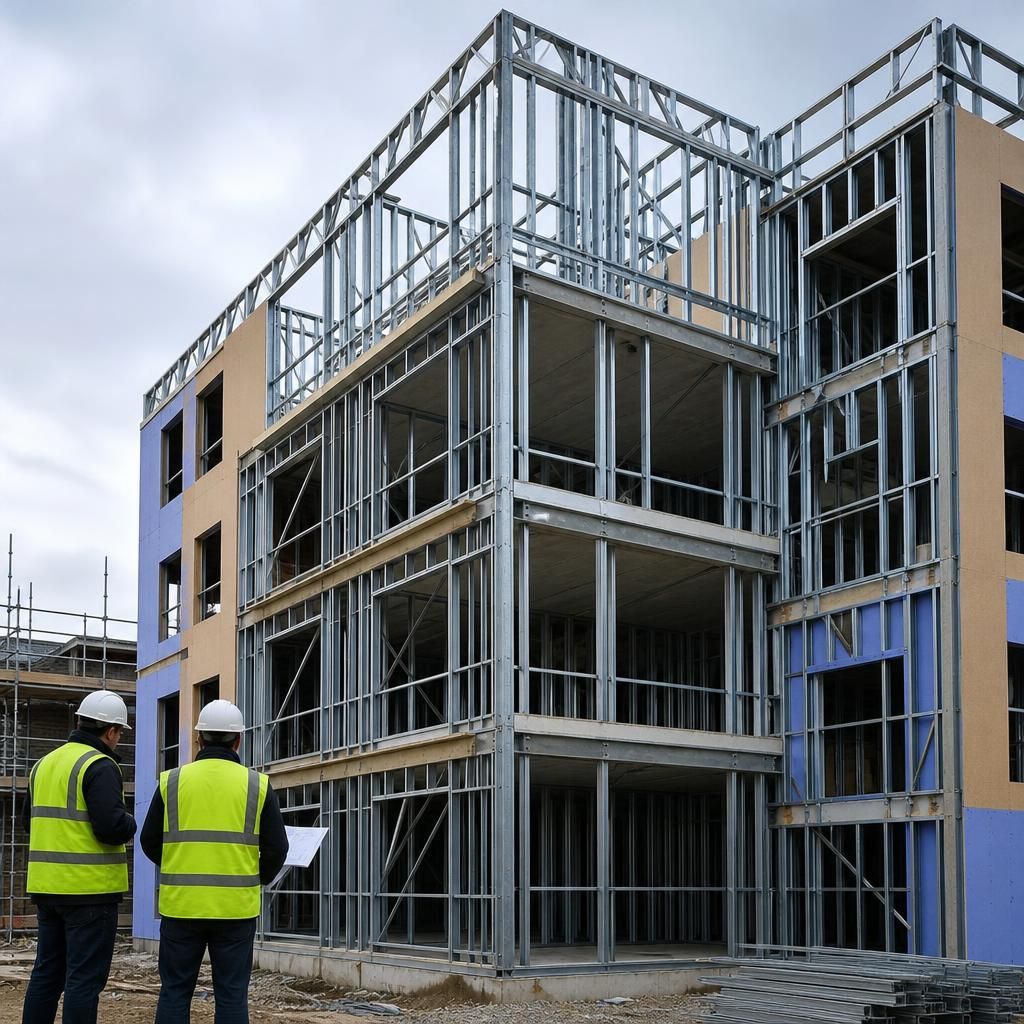
In multi-storey construction, light gauge steel framing may form either the primary load-bearing structure or an infill system supported by another frame. Load-bearing framing transfers floor and roof loads through the storeys to the foundations, while non-load-bearing panels primarily form internal or external walls and carry their own weight, finishes and attached components.
This distinction should be established at the outset because it affects the structural calculations, floor design, connection details and installation sequence. A building described as having light gauge steel walls is not necessarily supported entirely by light gauge steel; the drawings should identify which elements carry vertical and horizontal loads and which provide enclosure only.