
What role does bracing play in steel structures?
Bracing provides the strength and stiffness needed to keep a steel structure stable under lateral forces, such as wind, and during construction. It transfers these loads safely through the frame and into the foundations, helping prevent excessive movement, distortion or instability.
Bracing is the part of a steel frame that provides a defined resistance to horizontal forces and helps the structure behave as a stable three-dimensional system. It works with the columns, rafters, beams, connections and foundations to control movement, distribute forces and maintain the intended geometry of the building.
Without suitable bracing, individual columns and rafters may be strong enough for their direct vertical loads but still be vulnerable to sideways movement, twisting or buckling. Bracing creates stable panels within the frame, allowing horizontal forces to be carried to appropriate supports rather than relying on the bending strength of every primary member.
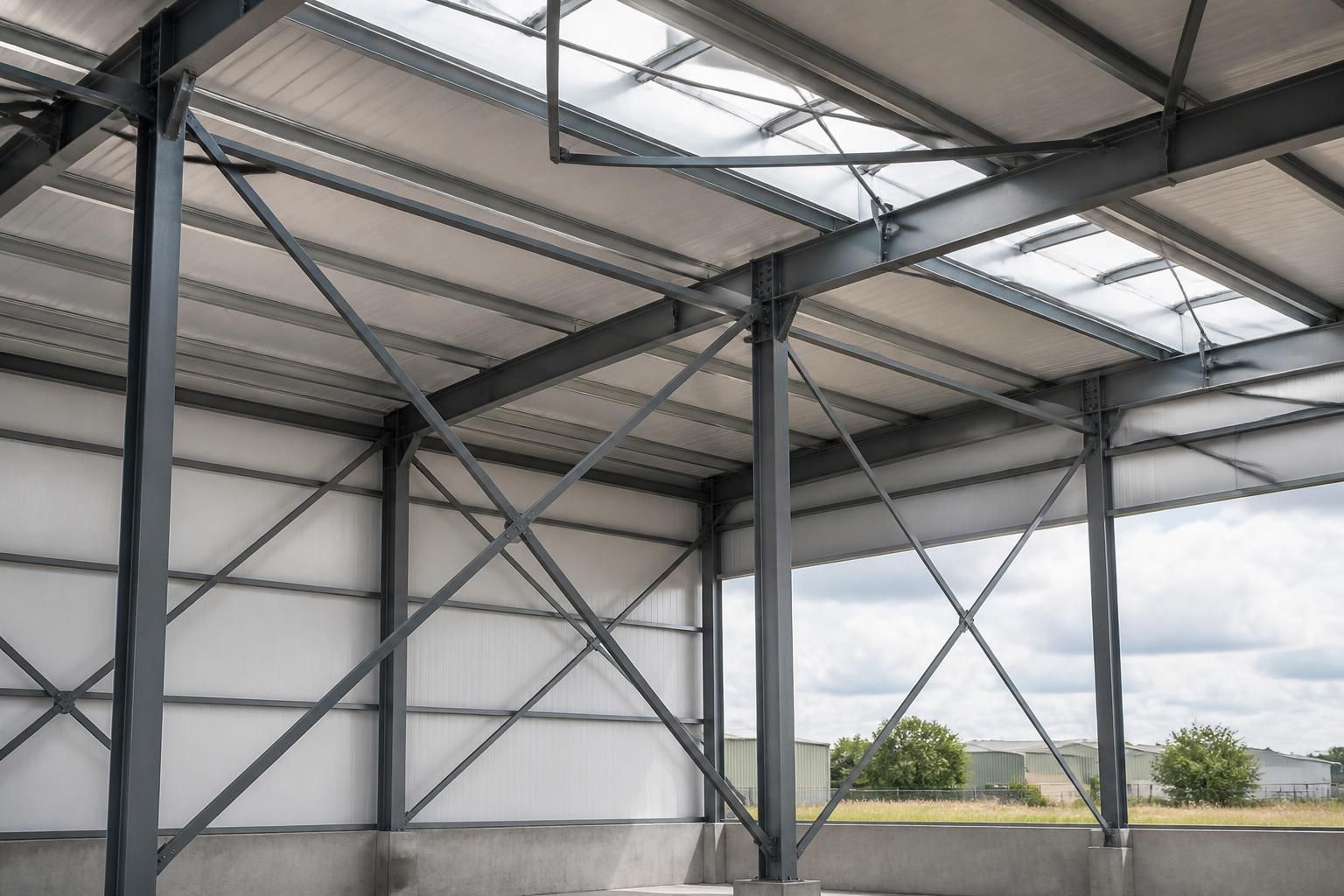
- Vertical wall bracing is commonly formed from diagonal members between columns. It transfers horizontal forces down the elevation and into the foundations.
- Roof-plane bracing links the roof structure and helps transfer forces between the rafters, roof-level restraints and braced bays.
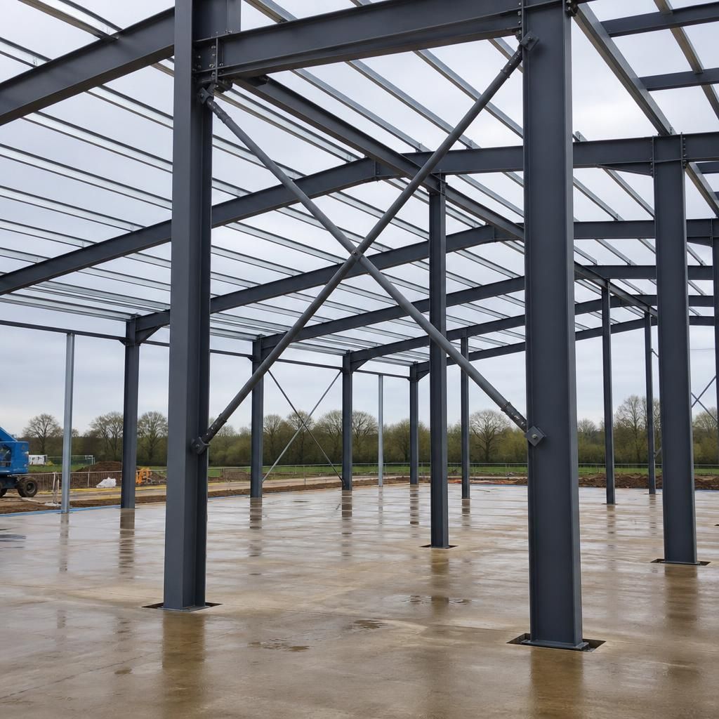
- Cross bracing uses two diagonals, often forming an X. Depending on the design and connection details, the members may work mainly in tension, with one diagonal becoming active for each direction of loading.
- Single diagonal bracing can be used where the load path, geometry and connection design allow it. It may work in tension, compression or both, so its slenderness and buckling resistance must be assessed accordingly.
- Portal or rigid-frame action can provide resistance through moment-resisting beam-to-column connections, although separate bracing may still be required for longitudinal stability, roof restraint or temporary stability.
The location of braced bays is a key design decision. Bracing should be positioned so that forces have a continuous, practical route through the structure. The designer must also consider access doors, roller shutters, windows, service routes, crane systems and other openings that may interrupt a diagonal. If a conventional braced bay is not possible, the design may require an alternative stability system, a transferred load path or additional frame action.
Bracing members can be made from flat bars, angles, hollow sections, rods or other suitable steel sections. The choice depends on the force direction, required stiffness, available space, connection arrangement and whether the member must resist compression as well as tension. A tension-only member needs protection against slackening and excessive deformation; a compression member needs checks for slenderness, local effects and buckling.
Connections are as important as the braces themselves. Gusset plates, cleats, bolts and welds must transfer the calculated forces without excessive deformation or local failure. Connection detailing should allow for fabrication tolerances, erection sequence, inspection and the movement expected under service loads. A brace that is theoretically adequate can perform poorly if its end connection is flexible, poorly aligned or unable to develop the required resistance.
Bracing also has a direct role during erection. Partly completed frames may not yet have the stability provided by roof sheets, wall cladding, permanent ties or all of the final connections. Temporary bracing, erection restraints and a planned sequence may therefore be needed until the permanent system is complete. This is particularly important for large agricultural and industrial buildings, where open elevations and long frame lines can leave substantial areas exposed before cladding is installed.
Designers assess bracing for more than one load case. Wind may act from different directions, while imperfections, erection actions, temperature effects, equipment loads and forces from cladding or roof systems can also influence the stability system. The analysis must establish which members are active in each case and verify the complete load path from the point of application through the bracing and primary frame to the foundations.
Bracing should not be confused with every form of restraint in a steel building. Purlins, side rails and sheeting rails can restrain individual members against local buckling, but they do not automatically replace a complete building stability system. Likewise, roof and wall cladding may contribute stiffness only where that behaviour is specifically justified by the design, connection capacity and installation details.
For a bespoke steel building, the bracing arrangement should be resolved alongside the general arrangement, planning elevations and fabrication information. Braced bays, member sizes, gusset plates, bolt groups and any required temporary works need to coordinate with doors, services, cladding and foundations. Clear isometric fabrication drawings help communicate these relationships to the people manufacturing and erecting the frame.
In practice, effective bracing is therefore a coordinated design solution rather than an add-on group of diagonal bars. Its success depends on the chosen stability concept, member capacity, connection detailing, restraint assumptions, erection method and compatibility with the building’s use. These factors are considered within the relevant structural design and fabrication requirements for the project, including the applicable UK and European standards.
Bracing must also be considered as part of the building’s fire strategy. When steel is heated, its strength and stiffness reduce, while restrained thermal expansion can introduce additional forces into the frame. A brace that forms part of the essential stability system may therefore need an appropriate fire-resistance assessment and, where required, protection.
Fire design should cover the complete arrangement rather than the exposed diagonal alone. The assessment may include the brace, its gusset plates, bolts, welds, surrounding members and the way forces are redistributed if one component becomes ineffective. This is why the bracing layout, connection details and specified fire protection need to be coordinated during design, particularly where the brace is located within a compartment or beside an opening.
Discuss bracing for your steel structure
If you are assessing a new steel building or reviewing an existing concept, discuss the proposed bracing arrangement with Buildings UK Ltd alongside the frame layout, access requirements and intended use. Their bespoke design service can incorporate the necessary stability information into planning and fabrication drawings.